SmartSDR v4.2.20 | SmartSDR v4.2.20 Release Notes
SmartSDR v3.10.15 | SmartSDR v3.10.15 Release Notes
The latest 4O3A Genius Product Software:
The latest 4O3A Genius Product Software and Firmware
If you are needing assistance with FlexRadio products, please refer to the product documentation or check the Help Center for known solutions. Need technical support from FlexRadio? It's as simple as creating a HelpDesk ticket.
TeensyMaestro

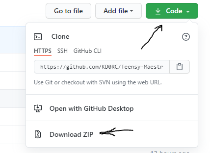
I recently finished my TeensyMaestro project and Dave, W4WKU is nearly done building TeensyMaestro #2. It seems stable enough at this point to open it up to anyone who would like to build one. To that end, I put the project out on GitHub: KD0RC/Teensy-Maestro-for-Flex-6000-radios (github.com)
There you will find a user manual, the .hex file (firmware object code), a program to load the firmware, a bill of materials, front panel graphics and some support files. Coming soon will be a builder's guide.
FlexRadio has graciously given permission to use this forum as a place to discuss the TeensyMaestro and get help if you decide to build one yourself. I am happy to help, to discuss and even entertain ideas for improvement (no promises...). At the moment, I am not releasing the source code, but I may do that at a later time. Note that this is not a FlexRadio product, it is my homebrew project so please direct questions and issues to me, not to Flex staff.
Thanks again to @IW7DMH, Enzo for his great Flex Arduino library, without which this project would not have been possible.
73,
Len, KD0RC
Comments
-
Will the schematic follow to put the whole shebang together . . . Parts ordered today.
Steve . . . WW1SS
0 -
Hi Steve, the schematic is there. It is the TeensyMaestro.sch file. If you bring everything back as a zip file, then extract all, you will have access to the .sch file. It can be opened in KiCad which you can get free here: KiCad EDA - Schematic Capture & PCB Design Software
I am new to both KiCAD and GitHub, so my apologies if I am doing things the hard way. At some point I will need to figure out how to gracefully put new releases out there. So if there are any KiCad or GitHub experts out there with guidance, I am all ears!
73,
Len
0 -
Got the schematic but it does not show the connections to the Teensy4.1
0 -
Hi Steve,
This is the Teensy 4.1. It is a bit confusing because of the pin numbering. It is a 48 pin board (just counting the pins around the outside of the board). The KiCad component shows a pin 49 which is not around the perimeter and also shows a block at the bottom which contains the ethernet pins, USB Host pins and some other misc pins. The card that comes with the Teensy does not show pin numbers, but shows pin functions. So if you compare the card to the schematic, you would look at the names inside the U1 diagram. If you want to know which pin number, use the numbers outside of U1.

Not shown are bypass capacitors (Dave, WK4WKU - thanks for noticing!). They are especially needed from key and paddle inputs to ground and from the keyer output to ground. .01 uf should be fine. I have not bypassed any other controls, but next time I have it apart, I will add them to every switch and encoder line. I will update the BOM and schematic to indicate them.
I hope that all made sense...
I am starting the builders guide today, so hopefully will have something ready to publish next week. In the meantime, don't hesitate to ask questions.
73,
Len
1 -
Hi Steve, well you are paying the price for being an early adopter... 🙂
I fixed the BOM to reflect some missing components (resistors, capacitors and a transistor) and I am in the process of fixing the schematic to show the bypass caps. I will re-post it today when I am done. In the meantime, these are the changes that include the most important bypass caps. I will make a note on the schematic that all switches and encoders should be bypassed, but I am not going to draw all 50 or so caps...
Full disclosure - On my TeensyMaestro, I have only installed the bypass caps shown below . I run 500 W on 160 - 6 with no RFI affecting the unit (YMMV). When I draw a big static arc from my operating desk when walking into my shack, that occasionally (25% of the time??) locks up the TeensyMaestro. I believe properly bypassing everything will solve that, or at least make it better. I do plan on fully bypassing the thing the next time I take it apart. Best to have the bypass caps right on the proto board, but it will be easier, and perhaps nearly as effective to bypass at the controls. Any Engineers want to weigh in on that?

73,
Len
0 -
Should be pretty easy. I used to work for Veeder Root in the digital systems division as a test tech and a service tech. Also worked for Scan Optics. They make digital scanning and imaging machines.
0 -
Ha! We used to use ScanOptics for check and other document imaging eons ago when I worked for Rocky Mountain BankCard Systems in the 80's and early 90's.
Well, it sounds like you should have a good time with it. I built mine with everything plugged together with jumper wires. My buddy Dave plugged the display in, but soldered everything else. If I were to do it over, I think I would take his approach to lessen the chances of wires rattling loose.
Len
0 -
Yea I was one of the setup engineers. Got a machine rolled around to us every 2 weeks and went through setup from start to finish.
0 -
Hi Steve,
Another step that I took was to stack the two multiplexers (with 6mm spacers between them). For the common connections (ground, +Vcc, etc.), I stripped a roughly 1/2" section of the pickup wire, and ran it though the top board to the bottom board, with a small piece of shrink tube on the +Vcc to ensure it wouldn't get shorted. Other end went to the Teensy board. This reduced the rat's nest of wiring.
I also put in-line connectors on the VFO encoder wiring. This allowed me to remove the encoders when working on the board - saved a lot of annoyance by not having those big encoders banging around.
If you want to use the jumper wires from Adafruit, be sure to purchase the male/male jumpers so that you can easily solder them to the Teensy and Display boards. I don't recommend cutting one end off to use these to connect the small encoders and switches to the Teensy board: the wire is very small gauge, and the insulation is thick and stiff, a recipe for broken wires at the solder points. For those connections I used 24-ga pickup wiring. With so many wires, and the Teensy breakout board somewhat confusing (as Len described earlier), it's easy to make a wiring mistake. if something doesn't work properly, first step is to check the wiring!
Good luck with the build
0 -
Two quick questions.
The 3.3v 250ma line is an output right?? Also where does the schematic show connections to the display??
0 -
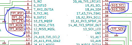
Hi Steve, yep, the 3.3v 250 ma on the Teensy board is where you get the 3.3 for the display, MUX boards and touch controller. The display connections are shown as flags and all start with TFT. The STMPE 610 connections start with 610.
There is a solder jumper on the back of the display board that needs to be closed for the SPI communications to work.

All of the 3.3 v pins on the Teensy are in common and all of the gnd pins are in common, so you can use any of them. I tied all of the gnd pins to the proto board ground rails and all of the 3.3v pins to the power rails. That gives you plenty of connection points.
73,
Len
0 -
Here is the aluminum engraved panel I'm having made
 3
3 -
Very Cool!! Make sure that the encoders to the left of the window fit - I had to move them slightly. Also make sure that the upper left encoder will fit in the box. Dave, W4WKU did a better drill pattern that I am getting ready to add to GitHub. My trick was to print the panel on plain paper and use it to cut holes in a piece of cardboard to test fit everything in the box.
Len
0 -
Hi Steve, here is the FrontPanel Express layout that Dave, W4WKU did. It provides very accurate placement of the controls (my layout may need some filing of holes). This also has the drill holes for the display and VFO encoder screws.
0 -
TeenyMaestro in the W4WKU HamVan. Temporary lettering on the front panel.
 2
2 -
Cool! TeensyMaestro #2 is on the air! I am running mine on V 3.1.12, Dave is running this one on V 2.6.2. I have not tried any other versions at this point, but these two are known good.
@ww1ssradio Steve, how is your build going? Have you received the parts yet?
73,
Len, KD0RC
0 -
Would be great to have some kind of kit :)
73 de Volker
0 -
Rest of my parts will be in today sometime.
0 -
Very interesting topic! Thanks for sharing.
Dave wo2x
0 -
@DL4RCE Hi Volker, If anyone wants to kit this up, I would be supportive. Would also be nice if someone with the experience wanted to create a PC board for it. The two challenges to building this are drilling and cutting the front panel and all the tedious wiring of the controls and display. The BOM has a reasonably complete list of components and links to buy them online, so that is not too bad. You still have to come up with a few small parts on your own.
@ww1ssradio Sounds good Steve. I recommend getting the ethernet and display working first so that you can verify the communications to the radio. Then as you wire in the encoders, you can test each one for proper rotation direction before you get too far along.
@David Decoons, wo2x Thanks Dave! Well, it has been a really rewarding project. I have built plenty of little ham radio gizmos over the years that wind up in the closet. This one gets used on a daily basis.
73,
Len
1 -
It would be a fairly expensive kit as the front panel alone cost $125 shipped in the anodized black and the labeling done. I am building mine on a solder proto board with headers and connectors for all the controls. May design a pc board after that.
0 -
Steve, you will have the best looking one yet! Getting the panel from Front Panel Express is a bit pricey, but for the money, you get a really great panel. I may do that myself some day. For now I saved the money and just drilled and cut my own panel. For graphics, I printed the front panel in black with white and red labeling. I cut it out with a very sharp hobby knife. I over-laid it with clear a PVC sheet from ACE hardware (cut with the same sharp knife). It took some patience to get a reasonable looking front panel, but I did it all with common hand tools.
Len
0 -
Couldn't you use a PCB for the front panel - much cheaper and they do look good.
0 -
Hi Lou, yep, sure could. I thought about that as I was designing my panel. A nice sandwich of a PCB for the electronics and one to provide a front panel with lettering would really be great. My low-end panel with a printed paper panel under a plastic sheet came out better than I expected, but not as nice as an engraved, anodized panel or a printed PCB. I could even see a 3-D printed panel and enclosure if someone were inclined in that direction.
I will be interested to see what other folks come up with. This thing can be built very minimalistically (is that even a word?). If all you want is Slice A controls without a display or keyer, it can be built that way with no changes to the software. A really small panel could be built to house it. I hope I made it flexible enough for others to get value from it.
73,
Len
0 -
Where does the touch screen controller wire in ??
0 -
First, on the STMPE 610 board, wire Mode to ground. Wire Vin to the 3.3 V rail and gnd to the ground rail. Wire the SDA and SCL lines to the Teensy lines shown on the schematic with flags starting with 610.
Len
0 -
Next, wire the X+, X-, Y+, Y- lines the the same labeled pins on the display board.
Len
0 -
Trying to load the file and I get . . . File contains data beyond chip size
Hex file is 1,359 kb but in verbose it says 484648 bytes 767% used
0 -
Hi Steve,
Here is a zipped version of the latest. Can you unzip it and see if this makes a difference in the load?
If you get the same issue, let me know and we can look at how you are loading it to see if I can spot the problem.
Len
0 -
It says file too large without the teeniest even being connected??
0


Leave a Comment
Categories
- All Categories
- 401 Community Topics
- 2.2K New Ideas
- 689 The Flea Market
- 8.6K Software
- 196 SmartSDR+
- 6.6K SmartSDR for Windows
- 200 SmartSDR for Maestro and M models
- 458 SmartSDR for Mac
- 279 SmartSDR for iOS
- 268 SmartSDR CAT
- 220 DAX
- 395 SmartSDR API
- 9.6K Radios and Accessories
- 106 Aurora
- 348 FLEX-8000 Signature Series
- 7.2K FLEX-6000 Signature Series
- 999 Maestro
- 58 FlexControl
- 872 FLEX Series (Legacy) Radios
- 975 Genius Products
- 482 Power Genius XL Amplifier
- 358 Tuner Genius XL
- 135 Antenna Genius
- 321 Shack Infrastructure
- 226 Networking
- 483 Remote Operation (SmartLink)
- 145 Contesting
- 847 Peripherals & Station Integration
- 147 Amateur Radio Interests
- 1.1K Third-Party Software