SmartSDR v4.2.20 | SmartSDR v4.2.20 Release Notes
SmartSDR v3.10.15 | SmartSDR v3.10.15 Release Notes
The latest 4O3A Genius Product Software:
The latest 4O3A Genius Product Software and Firmware
If you are needing assistance with FlexRadio products, please refer to the product documentation or check the Help Center for known solutions. Need technical support from FlexRadio? It's as simple as creating a HelpDesk ticket.
TeensyMaestro
Comments
-
Hi Phil, did you connect the 3 - 5 v line on the display board to one of the 3.3V lines on the Teensy board? If it is getting sneak power through one pf the other lines, you may see the white screen, but nothing else.
I don't think reloading will help, if it discovers the radio and shows the connected pop-up, then the software is OK.
Can you take a picture of the Teensy and display boards? I might be able to spot something that is amiss.
0 -
Forgot to mention... All of the ground connections on the Teensy are in common, and all of the 3.3 V pins are in common, so no need to connect them together. You do need to power the display from 3.3 V, not 5 V or you run the risk of knocking out the Teensy.
0 -
Hi Len,
The display board is connected to the Teensy board 3.3V line.
I had to do a bit of work yesterday so I'll get to looking at the project today and then send you a picture of the boards. I'm going to check the wiring again as well as for any solder splashes.
73,
Phil
0 -
It's alive! 😀
Found a link wire which was open circuit - not very impressed with the manufacturing quality of the connector wires I bought so I might swap them all out at some stage as I can't trust them now. Also found a tiny solder splash across two tracks on the breadboard - this was my fault of course.
Teensy seems to be happy now. Still no MUX chips delivered here, so I'll start looking at installing encoders but not the digitals obviously.
Thanks Len........
Phil
0 -
Hey, allright!! Nicely done Phil. Even without the MUX boards, you get a fair amount of functionality out of the encoders.
0 -
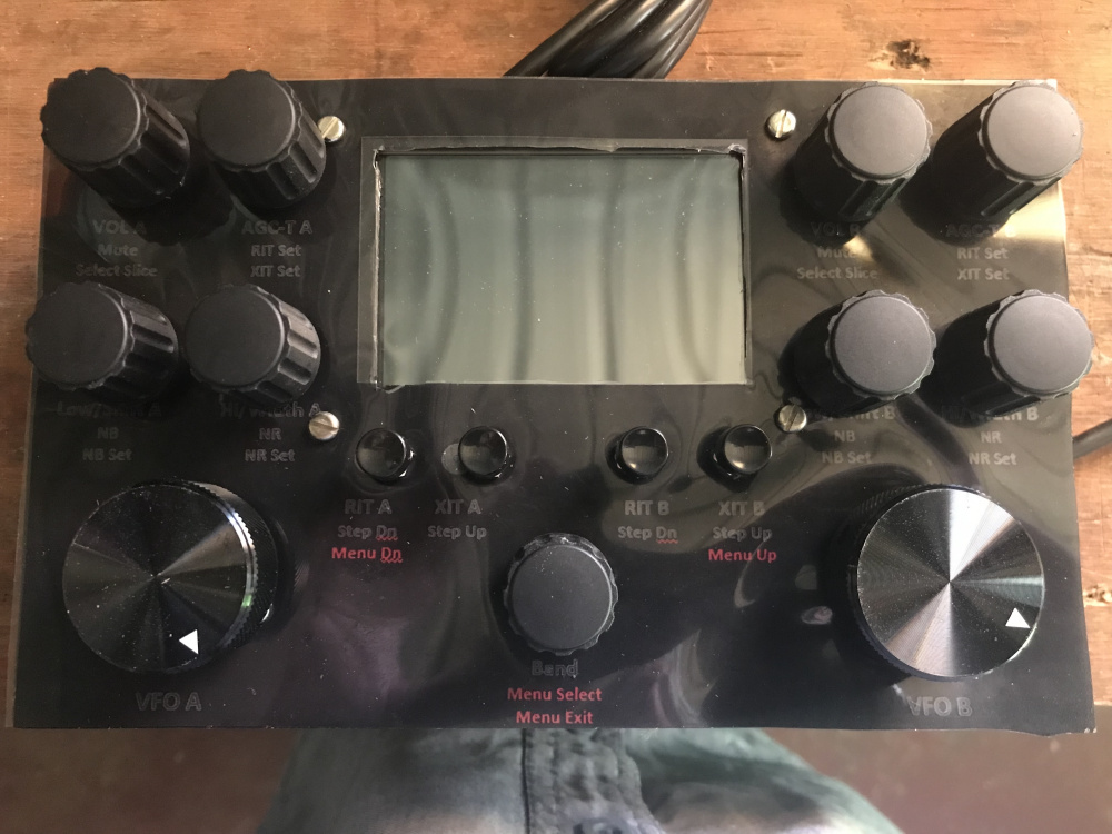
Sharp-eyed viewers might notice that Phil's display shows two slices, both labeled "A" and both TX indicators highlighted in red. This shows that Phil has two stations (GUI Clients) connected to his Flex using MultiFlex.
The first station to connect is shown on the left and the second on the right. With this arrangement, a pair of stations sharing a Flex and each having a TeensyMaestro can easily see where the other is operating.
I would guess that a pair of Maestros in SmartControl mode would behave the same way. If anyone knows otherwise, please correct me on this.
0 -
Len
In MultiFlex, the Flex Radio Server assigns slices on a first come first serve basis. So, the left portion has Slice (0), and the right has a piece (1), or maybe the other way around, but each is assigned the slice letter (A).
The problem arises in your situation, which GUI client is each slice number bound to? Have you considered building in a GUI client selector?
The Maestro, in Smart control, has a client selector on the front screen.
Alan. WA9WUD
0 -
Hi Alan, yes the TeensyMaestro has a client selector and is bound to whichever client is selected. This can be changed on the fly by the user with a menu item in the TeensyMaestro.
It sounds like the Maestro behaves the same way. I suspected this, but wasn't sure, so thanks for the confirmation.
0 -
TeensyMaestro V1.032 is now available on GitHub:
***************************** V 1.032 ***************************
 Added functionality to make the Encoder 9 (CW Speed/Menu Select) control user assignable
  (MMConfig and Misc Menu) to any of the following functions:
  CW Speed, Mic Gain, RF Power, Tune Power, WNB Level, Mon Level, VOX Level, VOX Delay, Band.
 Added code to accommodate non-US license classes (up to 5 classes) for Phone and CW/Digital.
A special thanks to Phil, VK4KW for suggesting both upgrades to the TeensyMaestro. The first part of this upgrade allows you to use the MMConfig.ini file to select default behavior for the CW Speed / Menu Select encoder. A menu item lets you select the desired behavior on the fly.
The second part is the ability to specify license class names in the configuration file. We are no longer locked into US license classes. These license classes are used to detect and report out of band operation.
Phil, I hope that your MUX boards are getting close, I am anxious to see how your build is going!
0 -
Just loaded the HEX file - all is well. 🤤
Thanks Len.
The MUX chips are nowhere to be seen as yet. The so-called 'tracking' shows them to still be in the USA, but they could be sitting in an aircraft or a customs hall somewhere and not have been 'scanned' yet so the website will only try to show the latest info / location that it has been told......
I'm now researching how to make the front panel of the Teensy a more professional finish than my usual efforts. I'm thinking that either a laser cut approach or possibly some sort of a 'sticker' would be the way to go. I've not idea about a company to provide either service however or if they would require the design in a particular file format to allow manufacture, so my search continues....
I'll let you know and send a photo or two when the MUX chips arrive. I've also not got the pushbuttons yet either..... 👍️
0 -
A quick question:
I've been trying to modify the text of the Panel layout FPD file to suit my needs - but it won't let me save the file.
Error message reads as:
3:04:20 PM: can't open file (error 2: The system cannot find the file specified.)
3:04:20 PM: Error while opening file: ''.
There is no text showing in the original design so I'm thinking that there is no text to show? Or is this a symptom of the hiccup, possibly?
Even before modifying the file it was upset and wouldn't let me save it. 'Save As' doesn't work either.
It refuses to export too, saying that it can't find the file - the one that is there and already open.
The file permissions seem OK and I'm logged in as 'Administrator' - so what am I missing? Is it protected for modification by an alternative means, possibly?
I'm using Front Panel Designer version 6.35.
73,
Phil
0 -
Hi Phil, I'm glad the new version is working. With just me doing the testing, I always have a little trepidation when I release code.
I am on jury duty this week so I won't be able to look at the front panel software until this evening. Front Panel Express provides that software, so you might want to reach out to them in the meantime.
If you want a really good looking (but expensive) front panel, Front Panel Express does an excellent job of custom engraved aluminum panels.
Sorry it is taking so long for your MUX boards and switches. That seems to be the new norm...
0 -
Hi Phil, finally getting back to you about the front panel. I can edit it, so I will try attaching a copy here to see if that makes a difference.
Be sure to extract all before invoking the Front Panel Designer.
0 -
Thanks Len.
This is what happens if I try to save the file. I extracted the original into a dedicated folder, started Front Panel Designer, opened the file and then tried to save it but to no avail.....

Very puzzling......
Phil
0 -
Hi Phil,
Hmmm... Not sure what the issue is. You might want to reach out to Front Panel Express and see if they have any suggestions. No one is making this project easy for you!
0 -
It's really weird.
I have installed the software twice, using different versions and get the same result. I ran the software as 'Administrator' and install to the default folder location.
I wonder if the 'work' file itself has to be located within a specific folder, else the software can't find it...?
0 -
Hi Phil, What happens if you start a new file, save it and see where it lands and then locate the one you are trying to open there.
Just a thought...
0 -
Hi Len,
We seek him here.... we seek him there...... we found the ****.
Solved it! The software is snotty about where it is happy to work with files. I created a folder on my Desktop and it happily saves to there without an issue. The bloke at Front Page is puzzled as to why the software is fussy, but at least I can work on the panel design to tweak it to my needs now.
Yay!
0 -
Excellent!! I can't wait to see how it looks. Do you have any of the controls wired up yet?
0 -
Hmm.
I'm not sure what triggered the '****', but anyway...... it's not the first computer / software puzzle I've encountered recently!
No controls are wired as yet. I'm keen to get the panel made, the bezel installed and then mount the encoders etc to allow wiring to happen. I've not yet received the push buttons yet either, but I could wire the remainder once I get the completed panel, but that's likely to be a while off as I've not finished the design yet let alone emailed the file for manufacture.
Phil
0 -
One suggestion; make a cardboard (or something) version laid out the way you plan to do with Front Panel Express. Temporarily mount and wire the display and a few controls to get a feel for the ergonomics. I went through 4 layout revisions before I settled on the layout that you see in my pictures. Some things that seemed logical at the time, were surprisingly poor... When I kept turning the wrong knob, I realized that I needed to re-think the layout.
Initially, I only mounted the slice A controls. After a couple of revisions, I mounted everything except for the CW message buttons. I made one more change after that and tested it for a couple of weeks. Then I took the plunge and cut and drilled the panel. So far - no regrets!
0 -
Well, I got the MUX chips delivered today.
No indication as to why they took so long. However, one of the boards is damaged and another has been requested. Initially, as I don't have a need for the CW part of the design, only one chip is needed. I', thinking of including the second MUX to allow future functionality that I'd like to experiment with.
The front panel people didn't want to supply only a one-off panel so I'm now resorting to printing the deign onto some clear plastic sheet which I'll glue onto the metal panel directly.
The gods seem to be against me on this project!!
Phil
0 -
Never a dull moment!! I am glad that you finally got at least one good MUX board. There are two unused spots on the first MUX, so you have some flexibility that way. The second MUX gives you an additional 16 buttons to go wild with when you are ready.
My front panel is just plain printer paper with a clear ABS plastic sheet over it. Not as nice as an engraved, anodized front panel, but it came out better than I expected.
Are you planning on printing on the back side of the sheet? If you do that, the lettering will be inside and stay protected. You just have to print a mirror-image.
0 -
It's been a while......
I finally got hold of the pushbuttons and the second MUX today. Seems like ages to wait for this stuff.
I've resorted to making my own front panel due to supply hassles, but I was wondering how other people were fixing the screen onto the back of the front panel? I see that the screen has some holes which might be used to mount via bolts, possibly? My metalworking skills are not wonderful so getting a professional finish is likely to elude me - unless someone knows of a good way to achieve it. I can't seem to find a suitable bezel to mount the screen within, which is a shame as this method would hide any less than wonderful metalworking issues. Maybe there's a supplier I haven't found yet that might supply them?
73,
Phil
0 -
Hi Phil, I used countersunk 4-40 (3mm would be ok) screws to hold my display in place. I used a nibbling tool to cut the rectangular hole in the front panel.
My trick is to print the front panel on plain paper. I cut out the display window with a sharp hobby knife. The paper is then sandwiched between the panel and a clear plastic sheet. The paper hides any anomalies in the cut out and the plastic protects the paper.
I use a black marker on the edge of the display cut out to reduce the reflection from the cut edge.
Hopefully that will give you some ideas.
0 -
Phil, VK4KW is making good progress on his TeensyMaestro. Here are some pics of what he has done so far. He will be heading into Brisbane next week where he plans on picking up a board to mount the various components, including the Teensy board. Once he gets that all wired up, he will be able to test it out.
I love the neat wiring harness that Phil built. Much nicer than my rat's nest!


 0
0 -
Len,
I have an article coming out in the Jan/Feb issue of QEX that describes the technique I used to create the front panels for my CTR2-Mini SO2R controller and CTR2-Mini+. It could easily be adapted to your Teensy Maestro design. Here are a few photos. I designed a printed circuit board in Kicad for the front panel and had it built with black solder mask and white silkscreen for the front labels. The board house cuts all the holes for the controls and could easily cut the hole for your display. You just mount the controls to the board and solder short jumper wires from the controls to the pads on the board. The pads are wired to the ribbon cable connector under the display. A ribbon cable connects the front panel to the I/O board in the base of the housing. On the SO2R controller I don't want any header pins visible on the top of the board so I used SMT headers. The cost of the PCB is only about $4 per board in quantities of 5 including shipping.

SO2R controller in a PacTec KEU-7 case

Mini+ controller in a PacTec KEU-5 case

The controls are mounted to the PCB and wired to pads on the PCB with short jumpers

The top panel attaches to the base with a ribbon cable
Just some thoughts for your consideration,
73, Lynn, KU7Q
2 -
Hi Lynn, that looks really nice! The CTR2 project has really come a long way since its inception. I have been following your adventures on groups.io and your CTR2 site. For those reading this, Lynn's CTR-2 Mini is a really cool radio controller that works with the Flex 6000 series (using the Flex API) and many, many other radios using CAT control. If the TeensyMaestro doesn't meet your needs, the CTR2-Mini might be a better fit. Check out Lynn's site here:
CTR2-Mini Overview – CTR2-Mini (lynovation.com)
I should probably just break down and design a couple of boards for the TeensyMaestro; one for the controls and one for the front panel, but I just haven't found the motivation to do it... If anyone has PC board design skills and tools and wants to tackle this, I would be very interested to see what you come up with!
0 -
TeensyMaestro V1.033 is now available on GitHub:
***************************** V 1.033 ***************************
Fixed bug where TeensyMaestro hangs instead of going into stand-alone keyer mode if there is no network
  connection.
Fixed to accommodate 5 digit software build numbers.
Added MMConfig.ini option to suppress spots generated by the TeensyMaestro. It does not affect spots
  from other sources.
Added code to cause VFO Tracking to be applied to SmartSDR or Maestro tuning.
Shout out to Dave, W4WKU (TeensyMaestro #2) for asking about the VFO Tracking when tuning with SmartSDR. I thought it would be useful to be able to use SmartSDR to independently tune the VFOs and use the TeensyMaestro to lock them together. Turns out that when they are locked, it is a real pain to have them get out of sync when using the mouse to tune.
Dave uses the VFO Tracking feature during CW hunt and pounce contest operation. He opens two panadapters, and zooms one way in so that he can see who is responding to the calling station. This way he can fine-tune where his transmit signal is compared to the pile-up. The other panadapter is zoomed a bit further out so that he can more easily spot his next target to pounce on without zooming the panadapter in and out. When he moves to the next station to work, both receivers move in sync so that he gets his magnified view without any goofing around.
Dave, Let me know if I have not characterized that correctly, or if you have anything to add.
I use the VFO Tracking feature a little differently. With only one receiver open, I set VFO A to a 100 Hz step size and VFO B to a 1 KHz step (in the TeensyMaestro, not SmartSDR). Then with VFO Tracking ON, I have fine tuning using the VFO A knob and fast tuning on the VFO B knob. For CW I use 10 Hz and 100 Hz steps. Brings me back to the days of Main Tuning and Bandspread...
0 -
Hi all,
Just a quick not to say that I am also building a Teensy Maestro.
Len was very kind and replied to my initial email with a lot of useful information.
As you can see I have so far managed to acquire the Teensy 4.1, ethernet adapter and a proto board. I also have some encoders etc, arriving today.
Hopefully over the weekend I can turn them into something useful.

Mike M0MDS
0


Leave a Comment
Categories
- All Categories
- 401 Community Topics
- 2.2K New Ideas
- 689 The Flea Market
- 8.6K Software
- 196 SmartSDR+
- 6.6K SmartSDR for Windows
- 200 SmartSDR for Maestro and M models
- 458 SmartSDR for Mac
- 279 SmartSDR for iOS
- 268 SmartSDR CAT
- 220 DAX
- 395 SmartSDR API
- 9.6K Radios and Accessories
- 106 Aurora
- 348 FLEX-8000 Signature Series
- 7.2K FLEX-6000 Signature Series
- 999 Maestro
- 58 FlexControl
- 872 FLEX Series (Legacy) Radios
- 975 Genius Products
- 482 Power Genius XL Amplifier
- 358 Tuner Genius XL
- 135 Antenna Genius
- 321 Shack Infrastructure
- 226 Networking
- 483 Remote Operation (SmartLink)
- 145 Contesting
- 847 Peripherals & Station Integration
- 147 Amateur Radio Interests
- 1.1K Third-Party Software