SmartSDR v4.2.20 | SmartSDR v4.2.20 Release Notes
SmartSDR v3.10.15 | SmartSDR v3.10.15 Release Notes
The latest 4O3A Genius Product Software:
The latest 4O3A Genius Product Software and Firmware
If you are needing assistance with FlexRadio products, please refer to the product documentation or check the Help Center for known solutions. Need technical support from FlexRadio? It's as simple as creating a HelpDesk ticket.
6400 Voltage Drop During TX
Comments
-
What current is the radio drawing when transmitting at full power?
0 -
Geoff AB6BT - I am not sure, there are no markings. The current wire directly connected to the PS is about 1/8 thick where as the Flex cable is ~ 1/4 thick.
Compared to my stock Yaesu and Icom cables, the current cable is about the same size. I believe it to be 12 Gauge and the Flex 10 Gauge.0 -
I believe the current test wire is 12 Gauge, it looks to be the same size as my stock Icom and Yaesu power cables. It has rings on the PS side and PP connectors for the radio.
I think I did do exactly as Mike asked:
With + PS and + Radio, the meter displays 0.054v. And -PS and - Radio, -0.035v. RX only. I did not test this with TX. Unless I an misunderstanding the process. I shoved the multi-meter probe into the back of the 4 foot cable connected Power Pole attached to the radio. One probe PS + and the other Radio +.
Is this incorrect?0 -
Hi Geoff, I was responding to the 13.70 vs 13.79 comparison.
So if the voltage drop of .87 is happening at the external connector, then the issue is either with the power supply or the cable/connectors.
1 -
Len…Copy that!
I'm out of here for now. Dinner time.
0 -
KD0RC/Geoff AB6BT/Mike-VA3MW - I hope I have provided enough testing/measurement results to help with root cause and potential remedy. Later tonight (when home from work), I will connect the Alinco PS w/10 inch power cable (also heavy gauge) to measure the PS and Flex side of the cable. I suspect the voltage drop on TX will be less as compared to the ~ 4 foot cable. I'll measure the cable length while it is disconnected.
Again, I am pushing the probes into the PP connectors that mate to the back of the radio. If this is incorrect, please provide guidance.
Will someone explain the greater drop in 12 and 10m when transmitting with a good ATU match? When I have access to a dummy load, I will test again.
0 -
It sounds to like the problem is in your Astron supply. I have a Samlex 1235M supply and the drop measured by FR Stack is only 0.2 volts at 100 watts on my 8600M.
0 -
Well,the way to test the power supply load regulation is to measure the voltage at the power supply terminals when the radio is in RX and then in TX. What is the difference at the power supply terminals?
0 -
Geoff AB6BT, I have done that and posted the results last night - Astron power supply.
Meter on PowePole back of Radio: 13.70 RX and 12.93 TX @ 70w RF power
Meter on PowePole back of Radio: 13.70 RX and 12.83 TX @ 100w RF power
* measured with multi-meter. Probes in the + and - of the Power Pole connections at the back of the radio.With the multi-meter connected to the back of the Astron power supply, voltage is: 13.79v RX & 13.75v TX.
Are you referring to something different?
Just now I connected the Alinco DM-330MV with a 9 inch power cord with + and - inline fuses terminated to power pole ends > connected to the 6400.20m, RF @ 70 watts - 13.8 RX and 13.4 TX.
If I adjust the Alinco to deliver 14.2v, I get 13.8V on TX.
The cable length is contributing to the voltage drop on TX, the longer it is, the greater the loss.
With the shortest cable I have, it is .4 volts.
Based on my limited understanding, voltage will drop under load, but how much is acceptable? Is it possible to have minimal drop with a longer thicker cable?
The voltage drop is more or less the same whether I use the Astron or Alinco.What is the math formula to calculate the drop over distance and gauge?
Another thing to mention - not sure if it is related …
My 6400 randomly drops, SmartSDR closes and when I start it up again, Smart SDR displays 'there are currently no radios available'. It was just up and running for the test with the Alinco, then suddenly dropped. When this happens, I have to power off, remove power cable for 15 seconds, and power on again. When I do, SmartSDR (still running on the PC) sees the radio and all is good, until it happens again. The 6400 is connected to the LAN with CAT5. This problem occurs with a direct connection too.
Power off & on doesn't solve, only removing the power cable for 15-30 seconds. As if it is flushing something from memory. This happens several times a week .. it is not the LAN or cables. I have swapped Ethernet cables so many times, switches, etc., nothing solves it but removing power.
With this occurring right now, I restarted SmartSDR without powering down the radio. It hung for minutes. When I did power down the radio (power button), a new 'radio connection failed - unable to connect to the radio, please try again' message pops up. It is like it may have seen it but could not connect to it.
Could this be a symptom of power problem? Other than the LAN, which I know is good, what else might cause the drop and no-return until the power is drained from the radio then restarted?
0 -
Possibly the problem is the power pole connectors themselves. Removing the housing look at the metal clip to see of there is any tarnish or corrosion. A good cleaning should help. Also, look at the crimp on the metal clip. You might need to add a bit of solder to the inner part of the crimp. Just don't let the solder flow down the wire past the end of the crimp. I had a similar problem with the 6600M I had. I also ended up opening up the radio and cleaning the pins on the internal fuse. ( automotive style) Once I did that, I no longer had a voltage drop even at full output using the original factory cable from Flex Radio.
James
WD5GWY
0 -
W4RXK…OK well you have shown the majority of the voltage drop is due to the resistance of the wire. (You can see the internal voltage using FRStack. Install it if you have not already.)
As I mentioned previously, just use Ohms law, E=IR. To determine the voltage drop, multiply the current through the wire by the resistance. You can determine the resistance of the wire using an AWG Table:
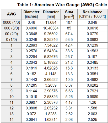
Remember that each wire (2-conductor) is part of the circuit so to determine the resistance of the wire you have to include both. So if your cable is 4' long calculate the resistance for 8' of wire.
You can connect an ammeter in one of the power wires to measure current or if your power supply has one use that.
0 -
Thank you everyone for the help here. It looks like it's the cable and the loss I am experiencing is common. Longer cable greater loss. I will open a new thread to address the radio disappearing as I described above.
Question for Trucker - you have zero voltage drop under full load of 100w? Your RX & TX remain constant? What did you use to clean the pins and connectors?
1 -
I used 200 grit sandpaper on the pins and Deoxit in the fuse sockets and a tiny drop applied with a Q Tip in each socket. I also inserted the power pole connectors in the mating connectors on the back of the radio and pulled it back out again several times.
If you have to go in and clean the fuse pins and sockets, it will take a while to do as you have to remove the top cover and if your radio has an ATU installed, you will have to remove the ATU as the fuse is located on the board underneath the ATU near the back of the radio. It is an automotive type of fuse. It's really not that hard to do, just time consuming and you have to pay close attention to some cables you have to remove to get the ATU out of the way.
And yes, I didn't experience any voltage drop on transmit at 100 watts. ( 13.8 volts) That was tested with a VOM at the power pole connectors on the back of the radio as well as in FRSack.
James
WD5GWY
0 -
First let me say that if you are getting full output from the radio, the voltage drop from power supply to the internal voltage of the radio is immaterial; this reduces to a pedantic engineering discussion .
James…If you are measuring is voltage at the end of the cable where it connects to the radio. The Power Pole connectors and the fuse/holder are not included in your measurmant.
It seem odd to me that you do not see any change in the voltage between RX and TX. There must be some difference unless you have zero resistance in the cable from the power supply to the radio.
Using FRStack, we can now include the Power Pole connections, the fuse/holder connections and what ever else there may be. Certainly these all have some resistance.
In addition, I would not recommend using an abrasive on th econtacts. The silver plating is only 1µm thick from what I can asertain. I do recommend DeOxit.
1 -
Geoff, thanks for your comments. The voltage at the power pole connectors was what I quoted. This was the original power cable that came with the radio when I received it in February of 2018. The problem I experienced was voltage drop that when keying up at 100 watts the radio would reboot. I measured the voltage and found it was dropping to 11 volts or so. Careful inspection ( disassembly ) of the power pole connectors ( after checking my Astron power supply which showed 14.1 volts at the terminals) showed a lot of corrosion on the metal. I wasn't too aggressive using the sandpaper. Just a few light strokes removed the corrosion. The here wasn't any voltage drop or the radio rebooting after I completed that and cleaning the pins on the internal fuse. The 13.8 volts I measured was at the power pole connectors on the back of the radio and also what FRSack showed. I ended up trading in my 6600M for a 8600M. Shortly after receiving the 8600M ( great radio) the Aurora AU-520M was announced. Since I had only had the 8600M a couple of weeks, I opted to return it for a refund and applied the money towards the AU-520M. While I miss the 8600M and even the 6600M, I do have a 5000A along with a few other radios to hold me over until the Aurora ships.
James
WD5GWY
0 -
James…OK, I'm glad it worked for you.
I stand by what I've said and I rest my case.
Enjoy the Aurora, it looks like a great implementation.
1 -
also, the input voltage to the flex can be in excess of 15 volts. Specs say 13.8 volts +- 15%.
0


Leave a Comment
Categories
- All Categories
- 401 Community Topics
- 2.2K New Ideas
- 689 The Flea Market
- 8.6K Software
- 196 SmartSDR+
- 6.6K SmartSDR for Windows
- 200 SmartSDR for Maestro and M models
- 460 SmartSDR for Mac
- 279 SmartSDR for iOS
- 268 SmartSDR CAT
- 220 DAX
- 395 SmartSDR API
- 9.6K Radios and Accessories
- 109 Aurora
- 348 FLEX-8000 Signature Series
- 7.2K FLEX-6000 Signature Series
- 999 Maestro
- 58 FlexControl
- 872 FLEX Series (Legacy) Radios
- 975 Genius Products
- 482 Power Genius XL Amplifier
- 358 Tuner Genius XL
- 135 Antenna Genius
- 321 Shack Infrastructure
- 226 Networking
- 483 Remote Operation (SmartLink)
- 145 Contesting
- 847 Peripherals & Station Integration
- 147 Amateur Radio Interests
- 1.1K Third-Party Software