SmartSDR v4.1.5 | SmartSDR v4.1.5 Release Notes
SmartSDR v3.10.15 | SmartSDR v3.10.15 Release Notes
The latest 4O3A Genius Product Software:
The latest 4O3A Genius Product Software and Firmware
If you are needing assistance with FlexRadio products, please refer to the product documentation or check the Help Center for known solutions. Need technical support from FlexRadio? It's as simple as creating a HelpDesk ticket.
TeensyMaestro
Comments
-
Oleg,
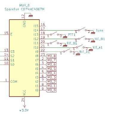
from the picture it seems you are using "my" PCB-design, and this is really based on the H/W V1, despite the PCB says V2.0, that reflects it was a major redesign of the PCB, but this was done 2023 way before the new H/W V2 which came this year.
The function buttons goes to J1 (i.e. into Mux 0)
/Lasse SM5GLC
 1
1 -
Lasse, thank you.
0 -
I just wanted to document my experiences with VFO encoder reliability in my TeensyMaestro, in case its of help to anyone else. The symptoms on my TM were that sometimes on powering up the TM, neither VFO encoder would work straight away. Sometimes they would start working after a minute or two, or I had to power cycle the TM to get them to start working. I also experienced "stuttery" response tuning until the TM had "warmed up" for a few minutes.
My TM is a V2 build using Simon's PCBs. The two VFO encoders are specified with a supply voltage range of 5-24v and when I measured various USB power supplies connected to my TM, the internal volatge presented to the encoders was around 4.8v. This worried me so I removed the 5v pin from the connector of one of my encoders so that I could run that encoder off a decent bench power supply. I measured the operation of the encoder and its current draw against voltage:
- stops working at indicated 4.77v
- works at 4.8v and above
- 14mA at 4.7v (not working): 66mW
- 15mA at 4.8v (working): 72mW
- 16mA at 4.9v: 78mW
- 17mA at 5v: 85mW
- 18mA at 5.3v: 95mW
- 20mA at 5.7v: 114mW
- 21mA at 6v: 126mW
- 26mA at 7v and above (current but not power limited): 182mW and up
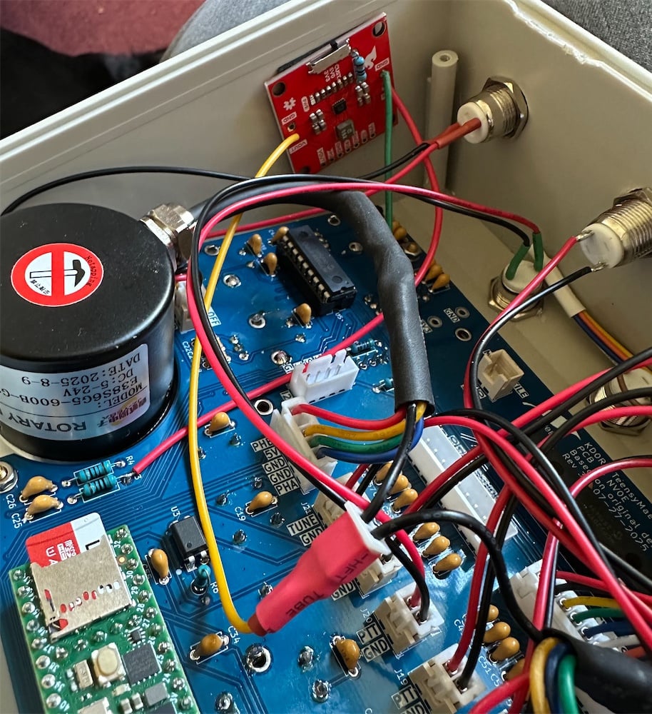
So this explained my problems - too low a supply voltage for the encoders. I know Len has reported his work down to 3.3v, but I guess it depends on how lucky you get with the manufacturer. So I decided to install a small buck/boost converter inside my TM to power the encoders at a higher voltage. This is safe to do because the encoder data outputs are open collector and those are still run at 5v from the pullup resistors on the PCB. I used this SparkFun PCB: which has the option to install a leaded resistor to set your output voltage. I used a 470kOhm which sets the output at about 6.4v. I made a flying lead with a 2 pin header and moved the encoder supply pins to a 2 pin socket, you can see the buck/boost converter on the side wall of the case:
Since I have made this modification, my VFO encoders have worked perfectly each time I have powered up the TeensyMaestro, so I've very pleased with how its working now.
I hope that might help if anyone else buys encoders that operate only at their specifications,
Best 73,
Jonathan G4IVV0 -
Hi Jonathan, thanks for that research and solution!
One small correction - the optical encoders are open collector fed from 3.3 V, not 5 V. Absolutely nothing on the Teensy can exceed 3.3 V.
0 -
Hi Len,
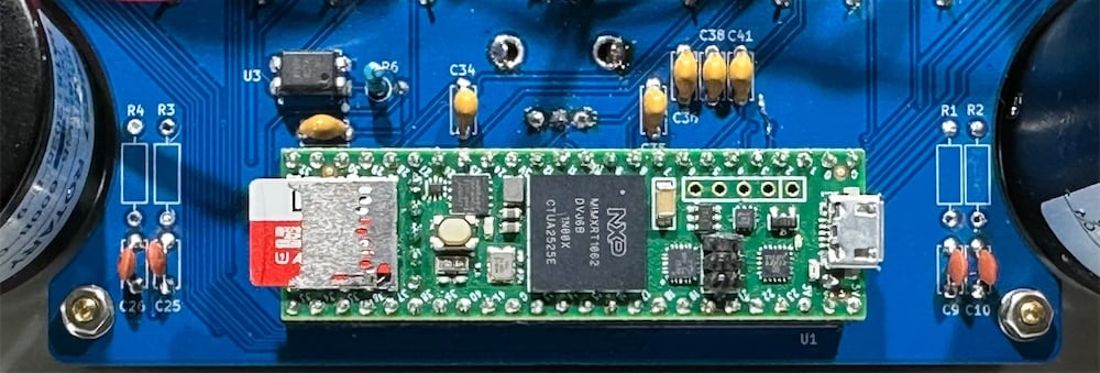
The rev 2 hardware has the encoder open collector pullup resistors connected to 5v:
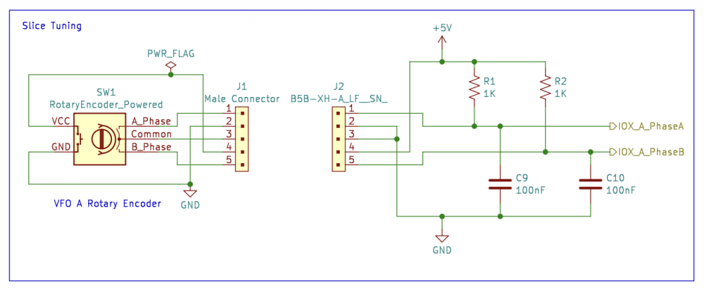
I just pulled mine apart to check, the top end of R1 & R2 is at 4.75v and the IDX_A_PhaseX pins are at about 3.9v high level, I guess being clamped by the Teensy inputs? There's certainly more than 3.3v directly measured on the Teensy 4.1 input pins.
This doesn't look right, I'm thinking about modifying my rev 2 board and moving the 4 pull-up resistors to 3.3v. I wonder what Simon thinks?
73, Jonathan
0 -
Hi Jonathan,
You're right, this doesn't look correct. R1, R2, R3 and R4 should be pulling up to 3.3v not 5v. Len and I are discussing ways to best mitigate the issue.
1 -
Thanks Simon,
Is it possible to just use the internal pullups in the Teensy or are they too high an impendance for these encoders? I'm happy to lift the 5v end of these resistors and wire them to the 3.3v supply in the meantime.
73 Jonathan
0 -
Great idea Jonathan. I originally designed in the external resistors for my point to point wired version with the encoders powered from 3.3 V.
With Simon's board powering them from 5 V, they may well be fine with the internal pull-ups. I will test this later today.
As I am writing this, my 8600 arrived! I will have to test the TeensyMaestro after I set up my new rig...
0 -
Hey, great news on the 8600 Len! I do hope you have as much fun as I've had with mine, it's a fantastic rig.
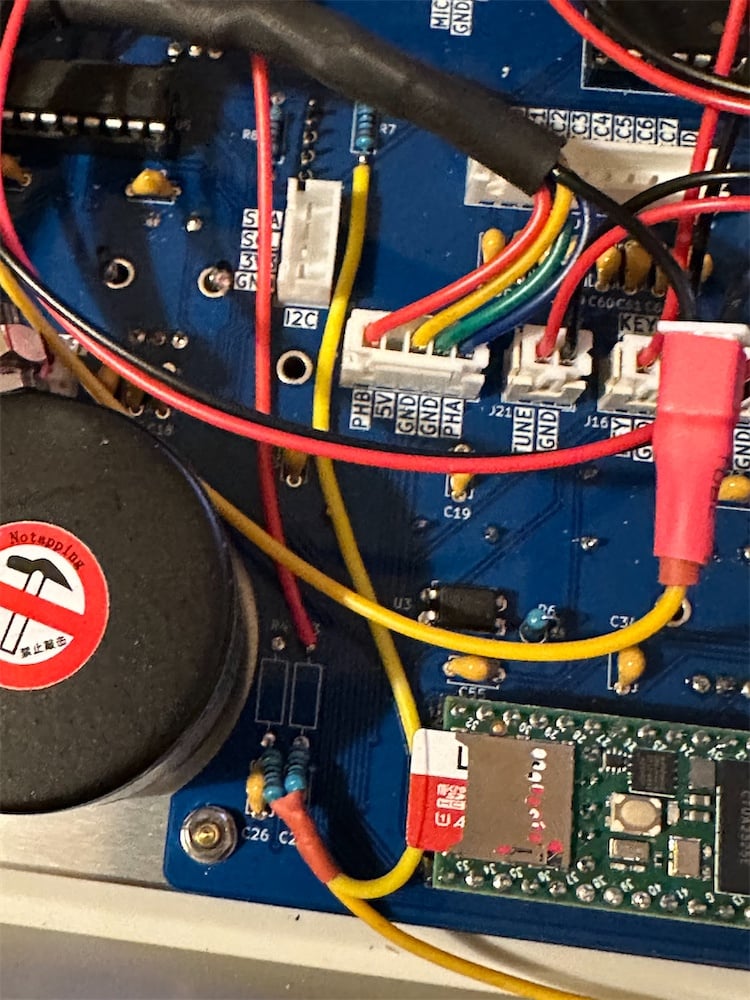
In the meantime I thought I'd see if its possible to do an easy wiring mod in case we need to keep the pull-ups. I managed to do this without having to disassemble everything. I lifted the 5v end of the 4 resistors and found I could pickup 3.3v from the end of R7. Folding the resistors back over the capacitors eliminates the risk of them touching the 5v pads:
Everything is working great, so at least we have that as a fall back mod. Will be interesting to see how you get on with enabling the internal pullups, as then we can simply clip out the 4 resistors.
But before that, get your 8600 up and running 😀
Edited to add: whilst I haven't found an official datasheet, indications from comments on the web suggest the internal pullup when enabled is around 47kOhm. This may mean the decoupling capacitors will be too large (time constant will be then ~5mS). So the capacitors may need to be replaced or reduced. Will be interesting to see if you notice any issues tuning with the 100nF's in place.
73, Jonathan
1 -
The Teensy inputs are not 5V compliant so having pull-up to 5 V seems a bit scary to me. I did ask Perplexity about internal pull-ups and it seems to depend on what pin is used on the chip, but apparently it can vary from 47 up to 170 kOhm! Also it is weaker than compared to earlier Teensy 3.x family. Using an external pull-up seem to me to be the safest route :)
/Lasse SM5GLC
0 -
Nicely done Jonathan! The software already sets the pullups, so no changes are needed to see if lifting the 1k resistors will work. If we really need the 1k pull-ups, your technique is what we will recommend.
The new rig is up and running! I even managed to check into the tail end of the Flex net on 20 meters.
1 -
be nice to see these changes documented with a Schematic changes to clarify.
NICE to hear you got your 8600, they are a nice radio.
73
Bret WX7Y
0 -
Hi Bret, Simon and I will completely document the change. We will provide thorough instructions to making it right. We still have a bit of testing to do, but it won't be long.
Yes, the 8600 is fantastic so far! I think the new ESC function isn't quite right, but I want to experiment with it a bit before I submit a ticket on it. It was nice to be able to import my 4.0.1 profiles from my 6400. Worked perfectly right out of the box.
0 -
Hi All,
After evaluating and testing several approaches to this issue, here’s a summary of the current findings:
Solution 1: Disconnect R1–R4 and rely solely on the internal pull-up resistors.
Result: Slice tuners function when tuning slowly, but pulses are lost at higher speeds. This approach is unreliable.Solution 2: Cut traces and add bodge wires to avoid desoldering components.
Result: While mechanically robust and technically viable, this method still requires lifting one lead of R1. I'm hesitant to recommend it due to the irreversible nature of trace cutting and the complexity of the instructions.Solution 3 (Jonathan’s suggestion): Disconnect the top leads of R1–R4 and run bodge wires from each to the bottom lead of R7, using heat-shrink tubing to prevent shorts.
Result: Though not ideal mechanically, this solution is straightforward and easy to understand.I've implemented Solution 3 on my board and will be testing it over the next few days. I’ve documented the modification thoroughly with photos. If Len and I are satisfied with the outcome, I’ll update the wiki with a detailed explanation. Ultimately, I plan to release a new schematic and PCB revision that resolves the issue cleanly.
On another topic: I tried to get Fedex to divert Len's 8600 to my house, but Fedex wouldn't listen to me. :)
2 -
Speaking of the 8600…. I discovered that with 4 slices open, the TeensyMaestro continually reboots itself.
My next priority (after applying Jonathan's fix) will be to allow any pair of slices to be used with the TM. I haven't thought this through yet, but I suspect that I will create a new menu for this.
If I get this working, you could have one TM on slices A and B and another on C and D. This is the configuration that wiped out my TeensyMaestro:
 0
0 -
I found and fixed the issue. I will do some more testing over the next few days, and if it seems stable, I will release it to GitHub. In the meantime, if anyone wants the beta version, let me know and I will post it here (but not yet on GitHub).
Next will (hopefully) be the ability to choose a radio, client to bind to and which slices are displayed (A - H). Currently, you can choose a radio by specifying it on the SD card. Going forward I will make that dynamic as a menu item. I will probably implement a Radio Menu and a Slice Menu in addition to the currently available Client Menu. I haven't given this a whole lot of thought yet, but these are my ideas for now.
0 -
I thought I'd try and dig a bit deeper to find out why my encoders didn't work at 5v and I had to install a buck/boost converter to get them to start up operate reliably. Whilst searching the web I found this video on YouTube where a chap investigates this problem with exactly the same encoder:
https://www.youtube.com/watch?v=JvUNzHatPu0
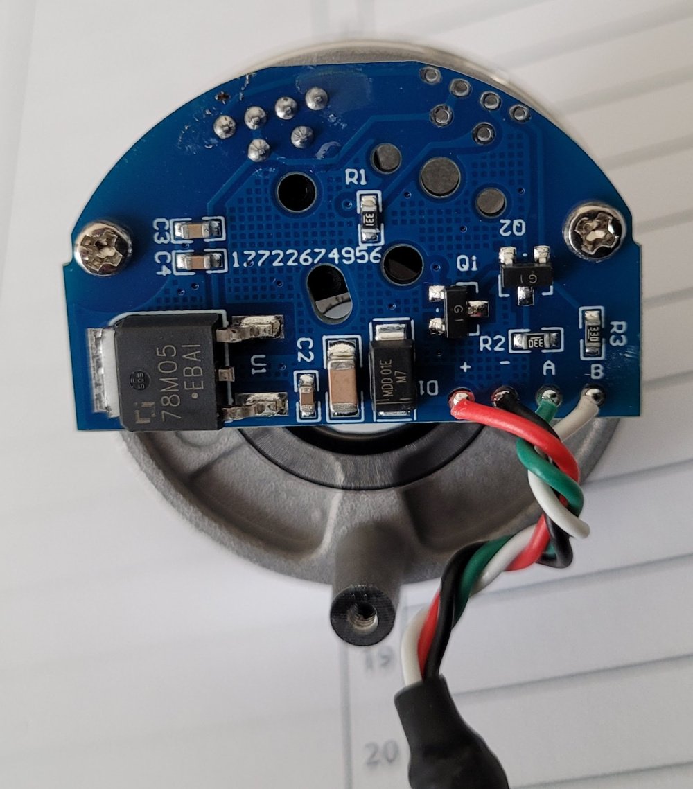
So I decided to open up my VFO encoders and sure enough:
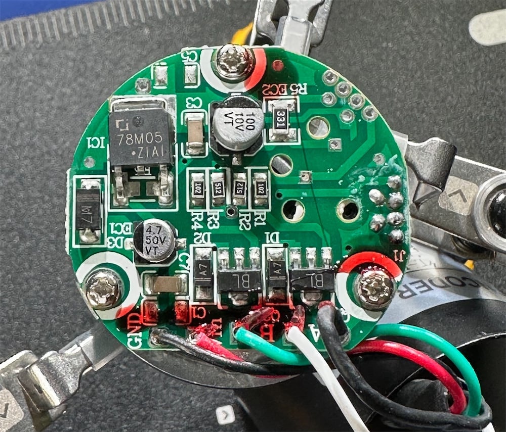
Well that 7805 explains why I had to feed in more than 5v to get it to work. In theory it should need about 6.8v to guarantee operation. Rather than simply wire across the regulator as suggested in the YouTube video I decided to remove the 7805's. This is pretty straightforward, the steps I used were:
- cut the two leads
- apply some fresh solder and soldering iron to the heatsink tab
- after a few seconds the solder will flow under the 7805 and it can be lifted off with tweasers
- then desolder the cut lead stubs and clean up
There are 0805 resistor pads conveniently located to bypass the 7805, but I didn't have a suitable low value 0805 to hand. I could have just shorted it out, but as I had some low value leaded resistors (10Ohm) I used those for some in-rush protection:
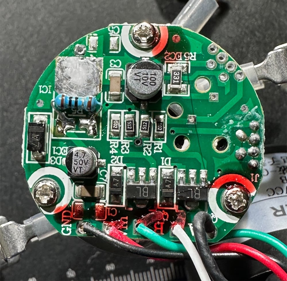
Final step after reassembling the encoders is to modify the voltage rating on the label with an indelible marker, otherwise I might forget in the future they can only be connected to 5v!
Now both my VFO encoders are working reliably on the original 5v supply and the mystery is solved.
73, Jonathan
0 -
Fantastic discovery, Jonathan! And a clever solution too.
Len and I haven’t encountered that particular issue, but it’s clear not all encoders are built alike. For instance, the ones I’ve picked up from Amazon lack the gland with a nut you mentioned, and there’s no rear sticker either. Now you’ve got me curious, I might just **** one of mine open to see what’s going on inside.
0 -
I thought I'd take one more go at simplifying the VFO encoder 3.3v Teensy interface fix.
SImon is right that relying on the internal Teensy pullups is unreliable because the time constant of the higher impedance of these internal pullups (we think somewhere in the range 50k-100k ohms) and the 100nF decoupling capacitors is around 5mS, much slower than using the 1k pullups.
I setup my 'scope to measure the risetimes. First, here's with 1k pullups and 100nF capacitors:
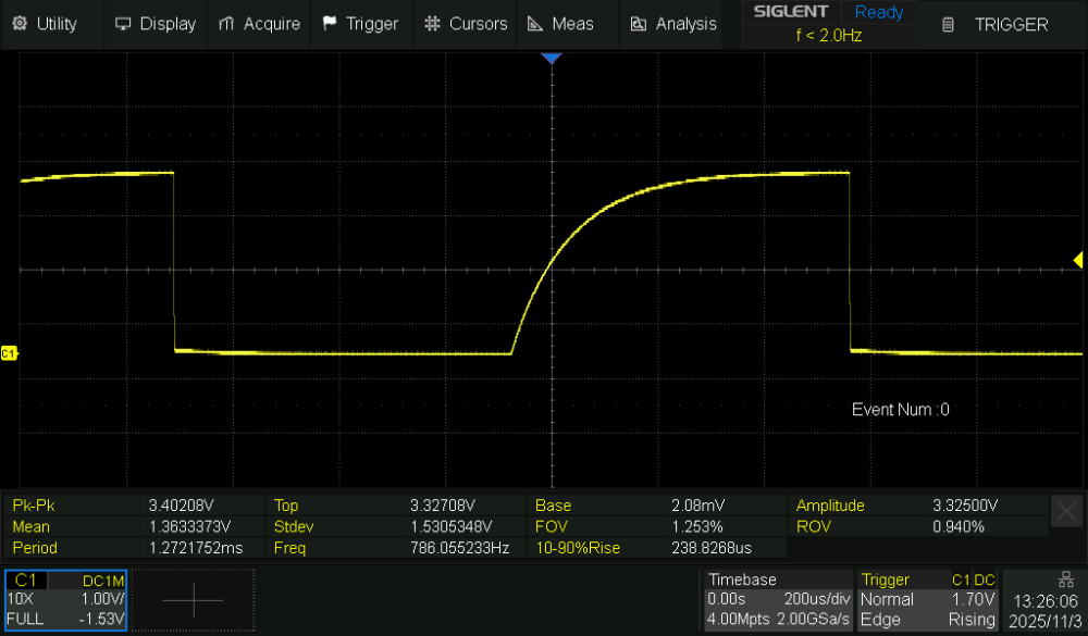
Interestingly I noticed that spinning the knob resulted in reduced signal amplitude, because at 600 pulse/rotation even this time constant is too large.
Removing the 1KOhm pullups, but keeping the 100nF capacitors has the expected effect (slower 'scope timebase for this capture):
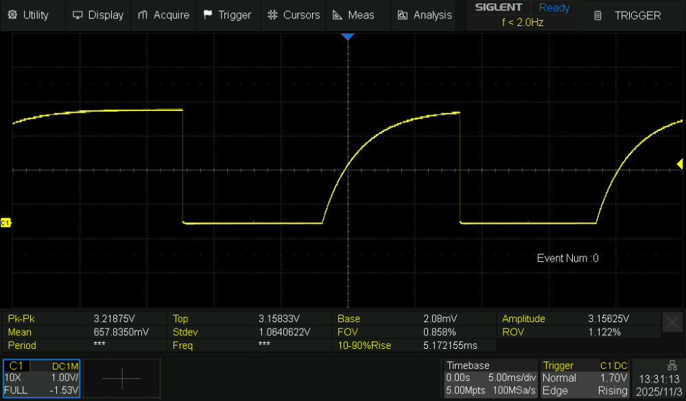
The rise time is measured at 5mS as expected and not useable.
But what if we reduce the capacitance? I replaced the capacitors with 1nF, which should give reasonable rise time and still provide some RF filtering:
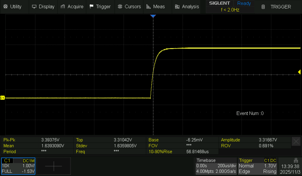
Bingo! 57uS rise time and a nice clean 3.3 volt logic signal from the encoder.
Encouraged by this I replaced all 4 encoder capacitors, so the final modification is really simple:
- remove the pullup resistors
- swap the 4 capacitors for 1nF ceramics
This is now working very reliably for me, and doesn't need any board modifications.
73, Jonathan
0 -
Very nice work, Jonathan. A much better solution that will be easy to explain in the build instructions. I'll try the same change today once I get done with that job thing.
0 -
Thanks Simon, it will be great to get another verification. Pleased to be able to help and also put my retirement to good use Hi.
73, Jonathan
ps. the more I play with my TeensyMaestro after doing this mod, I think the "fast spin the VFO knob" behaviour is improved with this smaller time constant. Previously I could see a little stutter when rapidly moving up/down the band. Probably limited by interrupt latency and API timings now.
0 -
Hi Jonathan. Excellent detective work! I will give it a try this morning. Thanks for all your help with this.
0 -
Hi Jonathan,
The PCB for my encoders looks very different than yours - a much simpler circuit. While there is still a 7805, I see mine doesn't have the A7 diodes (D1 and D2) that yours has. Are they connected to the A and B outputs on yours? Perhaps the forward voltage drop of 1.1v is problematic?
 0
0 -
Interesting Simon that yours does work with the 7805 in circuit - I guess how those regulators work at below minimum input voltage might well vary from vendor to vendor.
Sadly my photos aren't quite clear enough to be definitive on those diodes, but I'm fairly sure that they are connected between collector and emitter (ground) so are probably designed for reverse polarity protection. On my 'scope traces the open collector low voltage appears to be around 0.5v (sorry I didn't measure that) so I don't think there's any diode forward bias voltage offset in the A/B phase outputs. It just looks like a normal open collector output.
0 -
This is fantastic work - thanks to you all. I'll be cracking open my encoders when I get a chance and whipping out the 7805's. Wonder if I've got any 1nF caps kicking around…
Jonathan I swear this was all just an opportunity for you to use your fancy desoldering tool ;)
0 -
I did feel very happy to have a chance to get the vacuum gun out again Neil 😂
0 -
Which model do you have, Jonathan? I have a Hakko FR-301, it saves so much time. As long as I clean it regularly it works really well.
0 -
Yes its the same FR-301 Simon, a recent purchase, I just wish I had bought one earlier. Now I look forward to any opportunity to use it 😀 Also have a FX-888 iron which has been great as well.
Having now spent some more time using the TeensyMaestro with the 3.3v encoder mod using the 1nF capacitors I'm sure rapid tuning is better. Can QSY quickly up and down the band now really smoothly. Len has done a great job with the encoder interrupt handling and speed algorithm.
73, Jonathan
0 -
Ha! I have the same iron as well. Great news on the 1nF caps. I'll be replacing those later today too. Len's work on interrupt handling has made it very successful. As Neil pointed out, the contributions from the Flex Radio community with this project have been fantastic.
0 -
Hi Jonathan, I removed resistors R1-R4 and replaced the caps with 1nF values. The Teensy Maestro seems to be working very well. Once we've all tested for a few days, I'll update the wiki with a warning for existing builds and corrected build instructions for new builds. Thanks again for the solution.
0


Leave a Comment
Categories
- All Categories
- 391 Community Topics
- 2.2K New Ideas
- 664 The Flea Market
- 8.4K Software
- 157 SmartSDR+
- 6.5K SmartSDR for Windows
- 186 SmartSDR for Maestro and M models
- 441 SmartSDR for Mac
- 275 SmartSDR for iOS
- 265 SmartSDR CAT
- 206 DAX
- 386 SmartSDR API
- 9.5K Radios and Accessories
- 59 Aurora
- 297 FLEX-8000 Signature Series
- 7.2K FLEX-6000 Signature Series
- 974 Maestro
- 58 FlexControl
- 867 FLEX Series (Legacy) Radios
- 947 Genius Products
- 473 Power Genius XL Amplifier
- 347 Tuner Genius XL
- 127 Antenna Genius
- 308 Shack Infrastructure
- 216 Networking
- 470 Remote Operation (SmartLink)
- 142 Contesting
- 816 Peripherals & Station Integration
- 144 Amateur Radio Interests
- 1.1K Third-Party Software