SmartSDR v4.1.5 | SmartSDR v4.1.5 Release Notes
SmartSDR v3.10.15 | SmartSDR v3.10.15 Release Notes
The latest 4O3A Genius Product Software:
The latest 4O3A Genius Product Software and Firmware
If you are needing assistance with FlexRadio products, please refer to the product documentation or check the Help Center for known solutions. Need technical support from FlexRadio? It's as simple as creating a HelpDesk ticket.
6400 Voltage Drop During TX

Running FRStack to measure voltage & temperature. RigRunner 4005 using the 25A ports. I removed the cables & fuses and reinserted several times to ensure the connections were clean. No other devices are powered by the power supply - Astron 35M.
My 6400 is set for 70w output for digital modes (FT8/4). With the tuner active and good match, 70w RF power results in 70w FWD power in FRStack.
RX voltage is 13.7V - during TX, voltage drops to 12.2V. The voltage drop changes based on frequency.
6M: 13.7 > 11.9
160M: 13.7 > 12.2
Is this normal, dropping approximately 2 volts during transmit? What else can I check to determine why voltage is dropping?
Comments
-
No, that is not normal.
Start by measuring the voltage at the power supply. One possibility is that the supply has a problem. I would increase the output of the Astron to 14.2 V, even if the drop is not in the supply.
Next, I would bypass all of the gear between the rig and power supply to see if the drop is there. In other words, connect the power cable directly between the radio and power supply.
If none of that is the issue, you should pull and inspect the fuse in the Flex. It is buried under a board or two depending on options installed. Sometimes, just pulling and reseating the fuse is all it takes. There are YouTube videos on the procedure.
If none of that helps, or if you are not comfortable opening the case of your radio, submit a help desk ticket.
0 -
Yeah, I think this is about right … I went through similar investigation a while ago, and improved things a bit, but there seems to always be some drop and I think yours is not unusual.
What I did:
- turned up the voltage from my Astron power supply, such that the power-supply puts out 14.1V and FRStack shows me 13.8V internally. Truly, this is not hugely different from what you see, on RX.
- Tune: I have 13.5V (FRStack) with 10W output
- TX: 12.9V (FRStack) at 100W (20m) output. This differs notably from yours, but there is still voltage drop.
I use a West Mountain Radio RigRunner 4008H for distributing my shack power. When I dove into my own voltage drop concerns, I got out my tiny tub of MG Chemicals' Conductive Grease and went to town:
- I lightly scratch-cleaned every connection within my Astron (using a fiberglass "pen" designed for this purpose), and at the output of my Astron RS-35. Followed by De-Oxit spray-wash. Then conductive grease as I reassembled. The capacitor s.crew-terminals, the output bolts/washers/nuts, transformer and diode all got this, and whatever else I could find. I have two Astrons, so I could take one out-of-service for a week or more, and do this job right.
- I cleaned all PowerPoles associated with my RigRunner. Generally this meant spraying DeOxit into the "mouth" of each, then using a toothpick to introduce a small bit of conductive grease onto the out-facing "slope" of each PowerPole terminal. Then mate/unmate a few times to spread grease around. BTW - all my PowerPoles are crimped with the proper crimper, then soldered; terminals are positioned before crimping so that they are "relaxed" in a horizontal plane and shouldn't try to turn or twist when mated (to maximize conducting cross-sectional area).
- I pulled each and every fuse on my RigRunner, used the fiberglass-scratch-pen lightly, then sprayed DeOxit, and toothpick-coated each side of each blade with conductive grease.
- Lastly, I re-arranged my RigRunner connections, such that the incoming Astron power was right next to my FlexRadio connection. Lower-draw accessories are farther away.
I measured voltages at each connection along the path. I came to conclusions. My RigRunner and power distribution is best I can make it, but there seems to be some small amount of voltage-drop I cannot remove. My notes remind me that, for TX:
- I achieved 0V drop from inside Astron to the input of the RigRunner, both TX and RX. Before cleaning, this was a low 0.05V anyway.
- the RigRunner alone drops 0.25V internally, between connectors and fuses. Before cleaning contacts and fuses, this RigRunner drop was 0.5V (so, nice improvement).
- From RigRunner to FlexRadio, my 10ga soldered PowerPole cable and the mating connectors (ie including the other half of each PowerPole on the RigRunner and Flex) have 0.37V drop on TX. Before cleaning and re-arranging RigRunner, this drop was 0.94V (thus, link to Flex was the biggest "win").
- FlexRadio internally has 0.2V drop between terminal and wherever FRStack measures internally. I cannot change this.
Summary: by thorough and diligent attention to every aspect of your DC path, you may be able to lower your 2V drop to something like 1.2V or so. Helpful, to be sure, but not earth-shattering. And I found it satisfying to do the work and think about each step, despite the modest result.
Suggestion: quick and effective step: simply turn up your Astron output voltage. I researched all my other Astron-connected gear (TS-850, Antenna switch, LP-700 SWR, 2m Transverter, VHF amp, etc), and determined I must not exceed 14.2 volts. So, I dialled my Astron up to just below this point.
Note: the MG Chemicals' Conductive Grease is carbon-loaded for conductivity, and can make a spectacular mess. I highly recommend wearing nitrile gloves, and apply sparingly.
I similarly dove into, and pre-prepared my second Astron in the same way as the first. My first Astron is meter-less and required internal adjustment; Astron #2 has meters and external adjustment-knobs.
HTH!
0 -
I connected the 6400 directly to the output of the Astron 35-M. Still 13.7v RX and now 12.2 TX on 20m with 70w RF power using FT8. It was 12.2 on 20m before. The RigRunner and its connections are not the root cause.
With the 6400 connected to a Alinco DM330-MV dialed in @ 13.7v RX, TX drops to 12.4v using FT8.Using the TUNE option on the 6400 lower power the voltage drops from 13.7v to 13.1v.
I also swapped the power cable with another PP to PP cable and it made no difference.
0 -
OK, so it sounds like the voltage drop is happening in the radio. The next step is to pull and inspect the fuse. It is the most likely culprit. The blades of the fuse tend to oxidize over time. See Gord's post above about what he does to solve the issue.
13.7 is a bit low to start with, so I would increase your power supply output to around 14.2 volts.
If you are not comfortable opening the radio, you should submit a help desk ticket. Otherwise, check out YouTube videos for how to get at the fuse.
0 -
Len, as suggested, I increased the Alinco to 14.2v. TX drops it to 12.9v for a 1.3v drop. A similar drop when 13.7v. I have no issues checking the fuse. Is there an easy way to get to it or is it top & bottom cover removal?
0 -
It is top cover only, and then 1 or 2 boards depending on whether you have the built-in ATU.
The fasteners are Torx (T7 or T8 I think), so don't try to use a hex key.
0 -
I removed and cleaned the 30A fuse. I used CRC QD electronic cleaner on a q-tip to clean both sides of both fuse pins. The q-tip was clean, meaning, nothing visible after cleaning. I removed/replaced the fuse several times (approx 10 times) to make sure the contacts were good. No spray inside the radio. I sprayed the q-tip outside …
13.7v RX and 12.4v TX. It is the same with and without the ATU enabled. Still a 1.3v drop during TX. All according to FRStack. Again, using FT8 (enable TX).To summarize, different power supplies, different power cables, and removed/replaced fuse. No change.
Should TX voltage change during TX for different bands? I noticed on 40m, at 13.7v it drops to 12.2v. Drop changes slightly with band changes. FWD power per FRStack is approximately 1 watt more when TX voltage is 12.9 vs. 12.2.
For comparison, I have SDRMonitor and FRStack running. Both report the same voltages.
0 -
Have you measured the voltage at the power supply with a voltmeter during RX and TX? It is important to know where the voltage drop is happening.
0 -
Len, I have not done that yet, but will.
Checking with a friend who has a 6600. With an Astron 70 power supply and RF power set to 70 watts, his RX is 13.5v and TX is 11.6 (1.9v drop). More or less the same as me. Voltage drop under load.
0 -
Curious question .. what is the internal Ethernet port for? The main board with the external facing Ethernet port.
0 -
Your friend has some corrosion somewhere on his cabling that is causing that drop. You can test that by measuring the voltage on the back of the Astron while in TX and then again on the back of the radio. If it drops that much on the back of the power supply, the power supply needs service especially for a 70A supply.
I used to use one of those on my SGC500 Amp and at 500 watts it wouldn't even drop a volt.
Do not use FT8 to do the test. Run the Tune power to 100% and then put the radio into TX with MOX. You want to keep the test as simple as possible.
0 -
I would look at the Power cable and the Anderson Power Pole connectors as Power Pole's have a tendency of loss under loads. This starts at the Power Supply, then if you have a Rig Runner with or with out a fuse in circuit and of course the Radio Cable needs #10 wire with 45 Amp Power Poles.
At the factory the Radios where calibrated with a Power supply voltage of 14.2Volts if I remember right.
The internal Ethernet port are for the M version front Panel model of the Radio to plug into.
0 -
Mike, on 20m AM - with tune to 100, 13.7v RX and 12.2v TX. FRStack FWD power reads 93.2 with Tuner on and SWR 1.2. Voltage drops 1.5v from TX to RW.
The same process w/Tune Power:
@ 10w = 13.7v RX and 13.0v TX
@ 01w = 13.7v RX and 13.3v TX.0 -
Can someone do the same as Mike suggested and report their RX & TX voltages?
0 -
20M 100W output RX 14.6V TX 13.8V
0 -
Please do this, not in AM as that is only 25 watts.
- Tune Power to 100%
- 14.200Mhz
- MOX to go into TX on a dummy load
- Record the voltage on the back of the power supply
- Record the voltage on the back of the radio
- Record the FRStack voltage.
Since I am not at the radio, I did a test remotely. I have to depend on FRStack for the internal radio measurement. My NodeRed control panel measures the voltage on the back of the power supply.
This is in RX
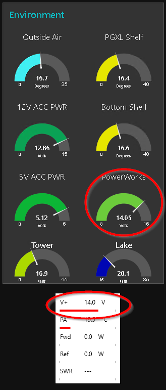
In TX:
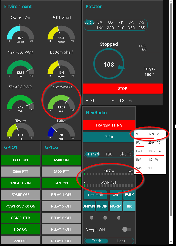
I had a 1.1V drop but was still able to product 107W output on the LP-100 watt meter.
The wattmeter in the radio is an actually minicircuit watt meters, so you can trust it to be accurate into a Dummy load.
Have you de-ox'd your power poles? This is something you should do annually.
De-oxing (cleaning and treating with an antioxidant compound) your Anderson Powerpole connectors helps keep them working reliably over the long term. Here’s why it’s a good idea:
- The contacts are made of metal, and over time they naturally oxidize, especially in humid or outdoor environments.
- Even a thin oxide layer can increase contact resistance, leading to voltage drop, reduced power delivery, and in severe cases, heating.
Let us know what you find.
73
0 -
These numbers are internal to the radio as reported by FRStack:
20M 100W output RX 14.6V TX 13.8V
Sorry I did not mention that.
0 -
Here is some interesting information regarding DeOxit. It also mentions silver dip which I have found to be very effective for severe cases. Note that silver sulfide is the predominant salt that forms on silver. It is not conductive. Sometimes just making and breaking the contacts a few times will remove the thin layers of silver sulfice and silver oxide.
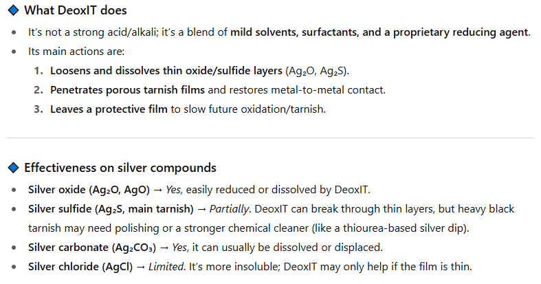 0
0 -
I used my 6600M almost daily for over seven years (recently traded in for 8600M) with the original power cable. Never measured the voltage drop, but it put out full power and operated perfectly (as far as I could tell) throughout.
0 -
0
-
@Mike-VA3MW - thank you for taking the time to help troubleshoot. I do not have a dummy load but will ask a local friend if I can borrow one and did a basic tests on a few bands with a multi-meter attached to the Astron output.
I noted that the voltage drop differs by band as reported by FRStack. My 6400 is set for 70w RF power on 160-6m. All bands tested below are 13.7v RX with the Astron direct connected.
ATU tuned to lowest SWR on FT8 segments. FT8 / WJST-X Enable TX w/power slide maximum. Measured in FRStack. 160-10 with MyAntenna 80-10m and 6m is a resonant dipole
160 - 1.3 SWR = 12.3v & FWD 58.0w
80 - 1.3 SWR = 12.3v & FWD 66.4w
60 - 1.1 SWR = 12.2v & FWD 65.5w
40 - 1.2 SWR = 11.9v & FWD 62.4w
30 - 1.1 SWR = 11.9v & FWD 63.3w
20 - 1.2 SWR = 12.0v & FWD 66.5w
17 - 1.1 SWR = 12.3v & FWD 68.0w - 13.79v RX & 13.75v TX (Fluke on PS)
15 - 1.2 SWR = 12.0v & FWD 66.6w
12 - 1.1 SWR = 11.8v & FWD 44.6w - 13.79v RX & 13.75v TX (Fluke on PS)
10 - 1.2 SWR = 11.1v & FWD 47.8w - 13.79v RX & 13.75v TX (Fluke on PS)
6 - 1.5 SWR = 11.8v & FWD 65.9wThe outliers are 12, 10, then 160 with larger voltage drops as reported from FRStack; however, the Fluke multi-meter does not display the same drop.
Is any of this useful? Is there anything else that influences power draw from a radio settings perspective?
It is common for voltage to vary on TX as band & frequencies change? I am curious about 10 & 12 as they have the largest drop.
What would cause 2.6v drop on 12m? Does antenna resonance (or lack there of) have any bearing on voltage draw?
Other than a dirty/oxidized power feed point, what else would cause such a drop? Should I expect the draw at the PS to be the same as the radio draw under TX? Meaning, the meters should be the same?I have swapped power supplies, radio power cables, and removed & cleaned the fuse with contact spray. No DeoxIT on hand. The only thing I have not cleaned is the both ends of the power cables and the radio end power poles. Will CRC Electronic Cleaner Spray make a difference or must I get DeoxIT? Which DeoxIT - there are several products.
0 -
This morning, I switched back to the original Flex power cable. The one I used during the testing above is smaller gauge. Not sure of the diameter, but visibly smaller than the Flex cable. FRStack results below. Multi-meter on the Astron unchanged 13.79v RX & 13.75v TX.
40 - 1.2 SWR = 12.3v / -1.4v drop
30 - 1.1 SWR = 12.4v / -1.3v drop
20 - 1.2 SWR = 12.4v / -1.3v drop
17 - 1.1 SWR = 12.7v / -1v drop0 -
Another way to test this is to measure the voltage drop across the cable with the VOM. Put one meter lead on the + of the power supply and the other end on the plus of the radio. This will measure voltage drop.
Next, so the same for the Negative lead. You might be surprised what you find.
1 -
For my next magic trick, I ran the power pole cable from the Astron direct to the radio. 13.7v RX and 12.9v TX on 20m @ RF power 70W. This cable is also heavy gauge, about the same size as the flex and about 4 feet long. 0.9v drop from RX & TX at 70w. With RF power @ max, RX is 12.8v.
With this non-Flex cable, I can get the probe into the radio side PP connector. With + PS and + Radio, the meter displays 0.054v. And -PS and - Radio, -0.035v. RX only. I did not test TX this way (don't know what I am doing here … ).
With the + & - on the PP connections on the back of the radio, RX is 13.70v.
With the + & - on the back of the power supply, RX is 13.79v.
I am loosing .9v when measured with the multi-meter
FRStack shows 13.8v and SDRMonitor is also 13.80v RX.I am confused, the voltage drop as measured at the radio is more or less the missing .9v under transmit load. Why are the API voltage readers reading higher than my multimeter under RX?
With the above testing posts, I had the power supply cable connected to the radio cable, approximately 8 feet.Given good cable, non-oxidized power pole connections or fuse connection, what do you estimate the drop to be underload?
With the 6400 connect w/4 feet of wire direct to the PS, what else can/should I do to reduce the voltage drop?
I am loosing sleep over this now. Am I chasing something that isn't a problem? If you were me, what would you do at this point or should I take ??? corrective action to further reduce the voltage drop?
0 -
W4RXK…Your voltage drop of 0.9 V is very similar to mine, as I mentioned above, at 0.8 V. I'll assume the radio is drawing 20 A with full power out.
Using Ohms law, R=E/I, R= 0.9 V /20 A =0.045 Ohms. That's only 45 milliOhms. That sounds reasonable to me. You have the power cable, the connectors, the fuse holder and whatever else. You can make some calculations based on manufactures specs regarding resistance on each component and add them up if you want.
As long as you are getting full power output from the radio I don't see anything to worry about.
0 -
It is not .9 v, it is .09 v. Now make that same set of measurements while transmitting to help understand where the voltage drop is happening.
0 -
Len,
Meter on PS: 13.79 RX and 13.77 TX @ 70w RF power
Meter on PP back of Radio: 13.70 RX and 12.93 TX @ 70w RF power
Meter on PP back of Radio: 13.70 RX and 12.83 TX @ 100w RF power
I read a post from a Flex employee (can't find it now) that all radios are tested at 13.8v RX and TX with no drop. How is this possible?0 -
Len…13.70 V - 12.83 V = 0.87…Yes?
I'm a bit confused as to where he is measuring the voltages. The last message states he is measuring at the Power Pole connectors. If that is the case then all the drop is between the power supply and the rear of the radio, so that eliminates anyrhing internal to the radio. The drop is still about 0.045 Ohms
0 -
Meter on PP back of Radio: 13.70 RX and 12.93 TX @ 70w RF power
Meter on PP back of Radio: 13.70 RX and 12.83 TX @ 100w RF power
* multi-meter probes plugged into the + and - of the power pole connection on the back of the radio - the cable ends attached to the backside of the Flex.
In other words ,the 'far-end' of the 4 foot cable when connected to the Flex to measure the voltage drop during TX.
When I have time tomorrow, I will connect the Alinco switching power supply to the radio. It has a heavy gauge wire about 10 inches long. Abut 3 foot x inches shorter than the Flex cable.0 -
What gauge wire are you using when you make this measurement? And how long is it?
And do as Mike suggested to see the actual voltage drop:
Per Mike…
Another way to test this is to measure the voltage drop across the cable with the VOM. Put one meter lead on the + of the power supply and the other end on the plus of the radio. This will measure voltage drop.
Next, so the same for the Negative lead. You might be surprised what you find.
0


Leave a Comment
Categories
- All Categories
- 388 Community Topics
- 2.2K New Ideas
- 658 The Flea Market
- 8.4K Software
- 156 SmartSDR+
- 6.5K SmartSDR for Windows
- 186 SmartSDR for Maestro and M models
- 439 SmartSDR for Mac
- 275 SmartSDR for iOS
- 265 SmartSDR CAT
- 204 DAX
- 386 SmartSDR API
- 9.4K Radios and Accessories
- 52 Aurora
- 297 FLEX-8000 Signature Series
- 7.2K FLEX-6000 Signature Series
- 970 Maestro
- 58 FlexControl
- 866 FLEX Series (Legacy) Radios
- 944 Genius Products
- 471 Power Genius XL Amplifier
- 347 Tuner Genius XL
- 126 Antenna Genius
- 306 Shack Infrastructure
- 215 Networking
- 468 Remote Operation (SmartLink)
- 142 Contesting
- 811 Peripherals & Station Integration
- 144 Amateur Radio Interests
- 1.1K Third-Party Software