Welcome to the FlexRadio Community! Please review the new Community Rules and other important new Community information on the Message Board.
The latest SmartSDR Software:
SmartSDR v4.2.20 | SmartSDR v4.2.20 Release Notes
SmartSDR v3.10.15 | SmartSDR v3.10.15 Release Notes
The latest 4O3A Genius Product Software:
The latest 4O3A Genius Product Software and Firmware
SmartSDR v4.2.20 | SmartSDR v4.2.20 Release Notes
SmartSDR v3.10.15 | SmartSDR v3.10.15 Release Notes
The latest 4O3A Genius Product Software:
The latest 4O3A Genius Product Software and Firmware
How to Receive Technical Support::
If you are needing assistance with FlexRadio products, please refer to the product documentation or check the Help Center for known solutions. Need technical support from FlexRadio? It's as simple as creating a HelpDesk ticket.
If you are needing assistance with FlexRadio products, please refer to the product documentation or check the Help Center for known solutions. Need technical support from FlexRadio? It's as simple as creating a HelpDesk ticket.
Looking for advise - Bandpassfilter - SO2R
Roland HB9VQQ
Member ✭✭
After my second cqwwrtty contest and first with Flex in SO2R my conclusion is I need bandpassfilters. In the contest I was using a Spiderbeam and a DXCommander. Both antennas worked great but not without interfering each other in SO2R. So for the next contest I want to improve the equipment and add bandpassfilters. I just need them for the contest bands.
Now what is the best option for automatic bandpassfilters which play nice and easy with my Flex 6600 ? I came across the BandPasser II from array solutions, which looks quite promising.
Any other options ?
73
Roland
Now what is the best option for automatic bandpassfilters which play nice and easy with my Flex 6600 ? I came across the BandPasser II from array solutions, which looks quite promising.
Any other options ?
73
Roland
0
Answers
-
Roland,
The best solution is better antenna separation and antennas with more directional characteristics. I subscribe to the ham radio adage that if you have 1 Euro to spend on your ham radio hobby then spend 75 cents on antennas and 25 cents on the rest.
With that said I use a Flex 6600 with great built-in bandpass filters and no interband interference. When I have a friend over and they are using the 6700 at the same time I do use an Array Solutions FilterMax IV on that rig. Using the FilterMax IV both the 6600 and 6700 can operate at the same time on different bands. You will need a band decoder scheme to drive it. Here is an inexpensive band decoder: https://www.unifiedmicro.com/decoder.html
Also, if you're not using a Flex 6600 I recommend you upgrade to that radio for the highest SO2R performance.
I'll be pleased to try and answer any other questions.
73,
Mack
W4AX
Alpha Team0 -
First some assumptions: While in SO2R you had each band on a different coax feed line. I'm assuming so because if not each band would mute when the other transmitted and you mentioned two totally different antennae.
Also each band was NOT in WIDE mode, thereby having two 7 stage band-pass filters active
Running multi-station, the "normal" is to have a band-pass filter between the amplifier and radio. While effective this does NOT eliminate harmonics and amplifier based noise (phase or pure noise) from being created (typically better than 60db) however -60db down from 1500 watts is 1.5mW into the antenna - That is still a loud signal. The only really clean way is to put 3KW filters between the amp and antenna (at several thousand dollars) so the bad amplifier products are suitably attenuated. If running without an amplifier then the filters in the driver/6600 should be plenty good enough for your use (providing not in wide)
Another problem I have seen is, at 100W+ power and especially at 1.5KW, is one transmitted signal may mix (rusty tower bolts or other environmental diodes) and create this noise. You would only hear this if a second RX is also active (hence the Multi-Station environment). The way to find these is often to Direction Find the RESULTING mixing products as this will direct you to the source of mixing rather than the transmitting antenna (however I have seen the source to be the transmitting antenna (normally coax joins or balun/common mode filters)
Don't remember hearing you during my RTTY operating schedule (at VE7FO)
Hope this helps and I'll check for your response1 -
Hi Roland
Some good ideas
You didn't mention which radio you are using? Like others have mentioned, a 6600 should fit the bill.
However, it is not related just to the radio, but good quality feedlines and RF chokes as well.
I posted something last week about changing out some RG8X for LMR400 made an amazing difference in my station. My noise floor got quieter and all my birdies disappeared. You don't want any RF making it into the radio and quality well shielded feedline is a big contributor.
I talked to a good RF friend of mine of Maple Leaf Communications (Bob, he used to be the chief designer at CushChraft) and highly recommend LMR240 for HF operations. It isn't as heavy as LMR400 and costs much less. Yet, its shielding properties are amazing.
Can you share your entire station layout including feedlines and lengths? Isolation is not all in the radio, but the entire station layout.
Mike va3mw
0 -
I only have limited space for the two antennas (1 horizontal,1 vertical) in my backyard, so I have not much choice when it comes to physical antenna separation. I do not run an amplifier, never will. Only running 100W max. Yes two seperate feed lines.
The radio is not in wide mode. I do have a 6600 already.
Still looking for a decent bandpass filter.Don't remember hearing you during my RTTY operating schedule (at VE7FO)"
My score is on cqcontest.net, SOAB LP :-)
Also I am using Messi & Paoloni high quality coax cables incl. common mode chokes at the feed point. 20m feedline between antennas and radio.0 -
Hi Roland
The 6600 has over 60db of isolation, so adding more BPFs might not fix your situation. Somehow the RF is making it in on a different path.
What sort of feedline are you using? Have you added chokes to the antenna end and the radio end of the feedline?
This is one filter I am aware of: https://www.dxengineering.com/parts/kmi-bf-100 if you want to give it a try, but there is no guarantee it will solve your issue.
As well, take some time and review this document from the YCCC. It is one of my bibles when it comes to RF Chokes and highly recommend that every HF ham read it. http://www.yccc.org/Articles/W1HIS/CommonModeChokesW1HIS2006Apr06.pdf
Mike va3mw0 -
What sort of feedline are you using? Have you added chokes to the antenna end and the radio end of the feedline?
Messi & Paoloni Coax including chokes. see above.They are installed at the feed point. stray RF is rather unlikely to enter the radio, because the radio is installed in the garage which is under the ground. The garage is built with reinforced concrete with loads of iron.
Thanks for the Link !0 -
Also I disconnected one antenna (vertical) at the feed point and trasmitted wit the other one (Spiderbeam). No more interferences. I did the same the other way around, disconnected Spiderbeam and transmitted with the vertical. Again no more interference.0
-
Here is a picture of the antenna setup, max separation with the avilable space
 0
0 -
Hi Roland
It will be interesting if cascading band pass filters solve your issue. Please keep us informed on how you make out.
Very nice looking QTH!
Mike1 -
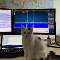
While we are at it, picture of the garage with the radio cabinet.


2 -
Hi Roland, We worked you in the contest last night, I believe on 40M. Had a little trouble decoding you due to a strong adjacent signal. Thanks for the QSO. I’m a relatively new Flex6600 owner , about 6 weeks now. I think my situation is similar to yours. I have a relatively small lot and not enough antenna separation. I have been using the Array Solutions Bandpasser II filters for a couple of years and found they worked well with my previous rigs, Yaesu Ftdx3000 and FT-991. I continued to use them when I installed the Flex and they do make an improvement allowing me to operate with high power. It’s easy to interface the filters to the Flex using USB to BCD cables plugged directly into the Flex USB ports. Another thing I found is that Bandpasser II filters also have a noticeable insertion loss on 15M that’s noticeable on transmit. I don’t see the same effect on the other bands. What I am finding is that the 2nd harmonic when transmitting on 80M and 40M is still causing a significant signal on 40M and 20M respectively. When operating at the low end of the bands that can put the harmonic signal within the desired receiver sub-band. The harmonic is still present even when operating low power, just a lower signal level. I plan to experiment with coaxial stub filters(quarter-wave shorted RG8 coax on 80M) to attempt to further reduce the harmonic energy by another 20-25dB. That’s relatively inexpensive compared to high power bandpass filters. There’s quite a few sources of info on the internet and Amateur handbooks for these. BTW...your QTH looks very nice. See you in other contests. Eric - NR4O1
-
Hey Eric,
I remember your callsign, thanks for the points :-) I own my Flex since June 2019 so we are in the same boat hihi, steep learning curve so far coming from an ELAD FDM DUO. Absolutely love my Flex, awesome what you ca do with it, just found the dueling CQ feature in N1MM during the contest. Learning by doing ...
Thanks for your info,exactly what I was looking for. The problem I have is mainly on 20 and 40m, having no Antenna currently for 80m. Simultaneous ops on 40 and 20 is not possible, interferences are too strong. No problem with 15m.
Good to hear your Bandpasser II does the job for you, I am hoping the same once I sorted out any possible flaws in my setup. Until now I cannot see any, just double checking every possible problem source. If nothing else helps, I will pull the trigger and order two of these Banpasser II Filters.
I briefly read about the stub filters you mentioned, might be worth to have a deeper look at it on the internet.
I hope I get this sorted until CQWWSSB in October.
Thanks agn and 73
Roland
P.S: Looking at the numbers on cqcontest.net, hw in the world can a SOAB LP do 2711 QSOs and 519 mults in a cqwwrtty cntst with the current solar cndx...? I am very very far away from those numbers hihi.
0 -
Just like Mike said, start with the common mode chokes. A good common mode choke has well over 5K of impedance, ideally mostly active rather reactive or complex. Adding some beads to the end of the coax unfortunately doesn’t do anything, except fatter profits for the seller.
The W1HIS paper is over 10 years old and out of date. The concept is sound, but building consistently high performance chokes is quite difficult. Take a look at the K9YC cookbook on chokes. Here’s a picture of high performance chokes, the left for 160/80 and the right for 40/20/15/10:
We use high quality Teflon coax that is expensive, but delivers outstanding performance. Choke the antenna end and the shack end.
If you have an ATU, activate it even if you don’t need it to match your antennas. The ATU acts like a TX filter, albeit not a great one. Don’t forget to choke the rotator controller cable as well as the DC power supply and all other wires/cables on the shack. Consider switching to a wireless keyboard/mouse combo to remove unnecessary wires in the shack.
Stubs work great, but you won’t be able to apply them to both antenna fees points. The Spiderbeam being a tribander makes it unsuitable as tuning out 40 will also tune out 15. You can however install a stub at the base of the 40 antenna and tuning out 20.
Assuming you stay low power, you want to make sure you have TX filters as well, not just RX. Question for Mike- are the 6600 filters TX/RX or only RX?
You also want to make sure that the shields of both coax cables are bonded together and grounded, both at the antenna end and the shack end. Bond the shack equipment together and connect to the AC power ground.
I run 1500w and the second harmonic is not an issue as long you stay ~25 KHz away. Smack on top of the second harmonic its signal strength is S5.
The Array Solutions (Hamation actually) filters work very well. I use them between the radios and the amps; there are 4KW filters for each band after the amps as well.0 -
Thanks for all your input so far. Trying to replicate the issues since I did not have time during contest and see what I can do.0
-
I could add to above that harmonics supression on the 1st harmonic is quite common and an effective solution is lump tuned stubs. They provide some 75-80 dBs of isolation.
What is this then? Nothing else than two stubs in parallell with a tuned coil inbetween. Not to difficult to built.
I have about 110 dB of isolation between my antennas for out of band signals. But the 40 m harmonic on 20 m is S9 without the lumped tuned stub. With the stub it almost dissipears. I am running a kW.
Not to forget also is rectification of signals in junctions (rotors, bearings etc). In my house I discovered that my LCD TV produced 20 m harmonics when sending on 40 m even with modest power (rectification inside the TV created double frequency signals). I pulled out the TV cord and all went away. It is very likely you may have this too.0 -
Karl, how would these stubs be used with multiband antennas like I'm using it? Do you have any links to docs how they are built ?
RFI Flooding .. http://lists.contesting.com/_rfi/2017-09/msg00008.html0 -
You will have to implement some sort of switching at the TX output. You may also want to read this book:
http://www.qrz.lt/ly2w/Ham%20Radio%20... and of course K9YC’s extensive work on stubs: http://audiosystemsgroup.com/StubPlac...0 -
-
I would strongly advise against such simple articles on stubs as they omit some seriously important details, such as: 1) Stub placement 2) Calculating stub length for a specific frequency and your own coax 3) Trimming/tuning stubs for a specific frequency using an antenna analyzer Having cut quite a few stubs myself, I have learned that stubs take a lot more effort than snip-snip.0
-
... but they come from the practice and they are in use and they do there job and that since many years ! Cant be so wrong.
Everything you can do better - that's real life :-)
0 -
Agreed, without proper test equipment, spectrum analyzer with tracking filter or graphical SWR analyzer it is going to be very difficult to get the desired results. Even with the equipment it can take hours of careful trimming.1
-
The way I see it, it is all about return on time and effort. That is, my philosophy is do it right the first time. And make sure you understand what you are doing. For example, stub placement is rarely even mention. Ditto for how to connect multiple stubs properly. Another example is the choice of coax. The common wisdom is to use cheap coax which has a lower velocity factor so you use less coax. What this common wisdom forgets to mention is that the expensive coax, with a velocity factor of 0.87, produces longer stubs that are much more broadband. In other words, people have the option to decide on their own trade off of cost vs. broadband coverage.0
-
Hi, as many below has said it is fairly easy to make one or double stubs and have them switched in line for different bands.
But as N2WQ points out you need to know WHERE you insert them. To complicate matters little bit more if you have PA you must know even more (what type of output network it has).
To make a long story short. You should insert a stub at a high impedance point along the coax line (the stub is a 0 ohm short at this point). If not the stub will not function properly. A OM2500A has a pi-L filter at output, with a high impedance at the 2nd harmonic, and here you may put a stub. For other PA it could be the opposite (low impedance). Next stub can then be placed on the next high impedance point (remembering that a stub produces a new low impedance point along the line).
A VNA is a must to measure the coax line properties. ARRL has free programs to analyse coax impedances as a funtion of length.
It is not complicated as it sounds but you need to do it in the right order as several has pointed it out.
An excellent artice is:Minimizing interstation interference by K9YC. It is on the web.
GL Kari SM0HRP0 -
Still chasing the interference Problem with SO2R.
Now I connected a Dummy Load directly on the Antenna Socket 2. Socket 1 is connected to a Antenna. I am transmitting 5W into the dummy load on Socket 2 and see this
is this normal ?
When I disconnect Antenna 1 I still see this


Now calling CQ Contest with only 5W into Dummy load, again no Antenna connected to
ANT1.


Of course it does not get any better when transmitting with 100W or even more.
730 -
Isolation is "only" 70db or something like that. What do you expect? External BP Filter will not help. I tried all kind of, 4o3a, OM power, low/high power, before/after amp. You can only reduce to the inherrent isolation which should be enough to not dmg your Flex. Volker0
-
Well with only 5W into a dummy load directly at the TRX I would expect to see no traces on other bands.0
-
No so. You'll have to do the math on the minimal discernable signal the radio detects and how my RF your dummy load and coax is leaking.1
-
There is zero coax involved just the dummy load.0
-
I think you'll find that a dummy load will also radiate RF. It is not able to turn all the RF energy into heat. I don't know what the number is, but I know we did studies like this when I was in college. It was impossible to not have any RF radiating.0
-
So I consider my obervations to be working as designed.1


Leave a Comment
Categories
- All Categories
- 398 Community Topics
- 2.2K New Ideas
- 678 The Flea Market
- 8.6K Software
- 191 SmartSDR+
- 6.6K SmartSDR for Windows
- 196 SmartSDR for Maestro and M models
- 456 SmartSDR for Mac
- 278 SmartSDR for iOS
- 268 SmartSDR CAT
- 218 DAX
- 392 SmartSDR API
- 9.6K Radios and Accessories
- 93 Aurora
- 335 FLEX-8000 Signature Series
- 7.2K FLEX-6000 Signature Series
- 988 Maestro
- 58 FlexControl
- 872 FLEX Series (Legacy) Radios
- 962 Genius Products
- 478 Power Genius XL Amplifier
- 352 Tuner Genius XL
- 132 Antenna Genius
- 317 Shack Infrastructure
- 222 Networking
- 480 Remote Operation (SmartLink)
- 143 Contesting
- 845 Peripherals & Station Integration
- 147 Amateur Radio Interests
- 1.1K Third-Party Software