Welcome to the FlexRadio Community! Please review the new Community Rules and other important new Community information on the Message Board.
The latest SmartSDR Software:
SmartSDR v4.2.20 | SmartSDR v4.2.20 Release Notes
SmartSDR v3.10.15 | SmartSDR v3.10.15 Release Notes
The latest 4O3A Genius Product Software:
The latest 4O3A Genius Product Software and Firmware
SmartSDR v4.2.20 | SmartSDR v4.2.20 Release Notes
SmartSDR v3.10.15 | SmartSDR v3.10.15 Release Notes
The latest 4O3A Genius Product Software:
The latest 4O3A Genius Product Software and Firmware
How to Receive Technical Support::
If you are needing assistance with FlexRadio products, please refer to the product documentation or check the Help Center for known solutions. Need technical support from FlexRadio? It's as simple as creating a HelpDesk ticket.
If you are needing assistance with FlexRadio products, please refer to the product documentation or check the Help Center for known solutions. Need technical support from FlexRadio? It's as simple as creating a HelpDesk ticket.
XIT visualization on TX slice
Options

Ron Parsons
Member ✭✭
Below is a screen shot of the XIT red bar on a FM slice.
The documentation in section 31.6.7 of the SmartSDR manual says:
"When RIT/XIT is set to something other than 0 the slice’s transmit filter bandwidth will be displayed on the Panadapter as a red bar. The bar is located behind the receive filter and will often overlap as shown below. Also, when RIT is adjusted a red dotted line will appear to show the original location of your receiver to where your slice will return upon zeroing out RIT."
The width of the red bar is smaller than either the NFM or FM transmit filter bandwidth. Also the transmit spectrum is not centered in the red bar.
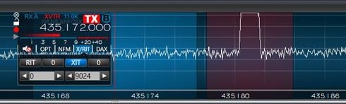
How is the width and position of the red bar related to the TX bandwidth and XIT?
Ron W5RKN
The documentation in section 31.6.7 of the SmartSDR manual says:
"When RIT/XIT is set to something other than 0 the slice’s transmit filter bandwidth will be displayed on the Panadapter as a red bar. The bar is located behind the receive filter and will often overlap as shown below. Also, when RIT is adjusted a red dotted line will appear to show the original location of your receiver to where your slice will return upon zeroing out RIT."
The width of the red bar is smaller than either the NFM or FM transmit filter bandwidth. Also the transmit spectrum is not centered in the red bar.
How is the width and position of the red bar related to the TX bandwidth and XIT?
Ron W5RKN
0
Answers
-
I know that we have checked the functionality of the XIT and RIT visualizations carefully on SSB and CW modes. I can't say that I have personally looked at it on FM. I would need to go take a look. This is likely a bug in FM mode. I've entered #3872 in our system to address this.
PS. Good to meet you in person at the office today.0 -
Eric,
Dave, W0DHB, has informed me that "In checking further, I don’t think the XIT visualization is correct for any mode other than CW and SSB, not just FM."
Thanks for the help yesterday.
Ron W5RKN0 -
Unless it has changed since I last did RTTY, it worked just fine for me in RTTY mode. But we have had one or two updates since then. I will check it this weekend.
Ken - NM9P0


Leave a Comment
Categories
- All Categories
- 401 Community Topics
- 2.2K New Ideas
- 690 The Flea Market
- 8.6K Software
- 197 SmartSDR+
- 6.6K SmartSDR for Windows
- 200 SmartSDR for Maestro and M models
- 460 SmartSDR for Mac
- 279 SmartSDR for iOS
- 268 SmartSDR CAT
- 220 DAX
- 395 SmartSDR API
- 9.6K Radios and Accessories
- 112 Aurora
- 348 FLEX-8000 Signature Series
- 7.2K FLEX-6000 Signature Series
- 999 Maestro
- 58 FlexControl
- 872 FLEX Series (Legacy) Radios
- 975 Genius Products
- 482 Power Genius XL Amplifier
- 358 Tuner Genius XL
- 135 Antenna Genius
- 322 Shack Infrastructure
- 227 Networking
- 483 Remote Operation (SmartLink)
- 146 Contesting
- 847 Peripherals & Station Integration
- 147 Amateur Radio Interests
- 1.1K Third-Party Software