SmartSDR v4.2.20 | SmartSDR v4.2.20 Release Notes
SmartSDR v3.10.15 | SmartSDR v3.10.15 Release Notes
The latest 4O3A Genius Product Software:
The latest 4O3A Genius Product Software and Firmware
If you are needing assistance with FlexRadio products, please refer to the product documentation or check the Help Center for known solutions. Need technical support from FlexRadio? It's as simple as creating a HelpDesk ticket.
Key in, TX Delay and CW Delay (holdoff)

I there a timing diagram that shows the relationship between the key down, TX Delay and the CW PTT return to RX. Using an 8600 and PGXL. The manual is not clear and a diagram would be great.
I'm not clear about when the RF is actually output to the antenna.
Is the start of the CW signal delayed by the TX Delay?
- At 30 WPM a dit is 40ms. If I set the TX Delay to 30ms, does the RF output begin at 30ms with the complete 40ms dit?
2. If the CW delay is 15ms (PTT returns to RX) does the dit complete or is it truncated?
Thanks.
Answers
-
 Mike-VA3MW Administrator, FlexRadio Employee, Community Manager, Super Elmer, Moderator adminOptions
There is a timing chart, but I can't put my hands on it at the moment.
Let me if I can explain this accurately.
TX Delay is added on to the end of the Longest of TX1, 2 or 3 delay.
Yes, the CW is delayed and buffered by the addition of those 2 times. The return to RX is after the completion of the CW elements so not truncated.
You can test this by setting up a 1000ms delay and listening / seeing what happens (as a test).
0 -
Hi Mike,
Lets say I have only the TX delay set.
The RF output starts at the end of the TX delay and ends at the sum of the TX delay and the CW delay. Is that correct?
The CW delay is triggered on the rising edge of the key input but it is not applied until after the TX delay period. Is that correct?
So, using the numbers in my original post, the TX delay plus the CW delay (30ms + 15ms = 45ms), when PTT returns to RX, should allow the dit to be completed.
The radio will unassert PTT between characters for this scenario,
Does that make sense?
I believe that at sometime in the past I connected a scope to the key input, a sample of the RF output, and the PTT but I couldn't find my notes with the result. Thus my question.I may have to try again.
Thanks.
0 -
Mike-VA3MW Administrator, FlexRadio Employee, Community Manager, Super Elmer, Moderator adminOptions

 1
1 -
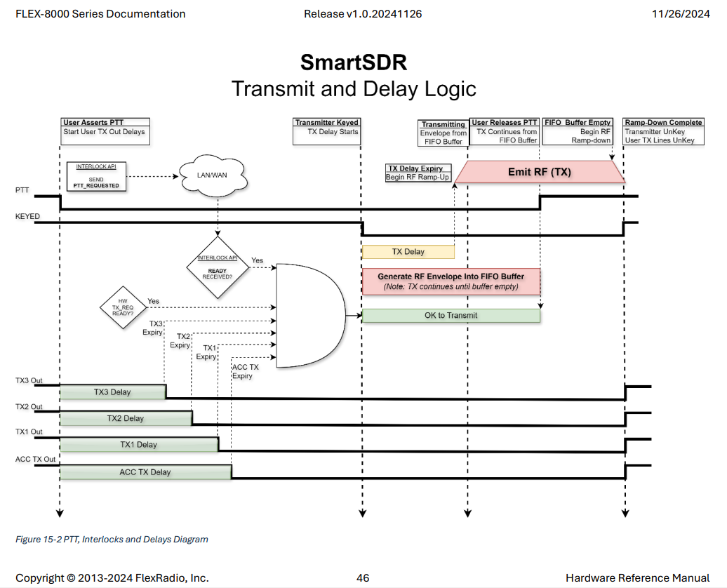
OK, the timing diagram is mostly complete.
At the top right of the diagram is a block labeled "FIFO Buffer Empty" which starts the RF ramp-down.
The CW holdoff delay is not shown in the diagram.
What I'm trying to understand is the relationship between the FIFO Buffer Empty state and the CW holdoff delay. Is the CW delay implemented after the FIFO buffer is empty? If not where?
Thanks.
0 -
Mike-VA3MW Administrator, FlexRadio Employee, Community Manager, Super Elmer, Moderator adminOptions
I have asked someone to respond from engineering.
Is there a problem you are having here?
0 -
That is a good question, Geoff. One that will take a bit of investigation to answer. Watch this space - it may take a day or two.
0 -
Thanks Mike and Dan…Standing By.
0 -
Hi Mike and/or Dan,
Do you have any info regarding my question?
Thanks!
0 -
Hi Mike and/or Dan,
Any response yet? If not, when do you think I can get an answer?
0 -
Hi Mike and/or Dan,
As Dan said …"It may take a day or two" and we're coming up on two weeks.
Any response yet? If not, when do you think I can get an answer?
Is there any hope, or should I just give up?
I can set up a test myself but I was hoping for an official response.
Thanks.
0 -
Geoff, our apologies - this fell off my radar. I'll ask again
0 -
Thanks Dan.
0 -
Here is the response:
The Transmit and Delay Logic diagram illustrates the general PTT-driven transmit flow used for voice and data modes. CW operation follows the same high-level transmit pipeline, but includes an additional timing behavior known as CW Delay (sometimes called holdoff).CW Delay is a transmit hold time that keeps the radio in the TX state after a CW element completes, rather than immediately returning to RX. The purpose is to prevent unnecessary TX-to-RX-to-TX transitions between closely spaced CW elements, characters, or words. This is especially important at higher CW speeds and when operating with QSK enabled you would see 0 for CW Delay.
Conceptually, CW Delay occurs after RF emission has begun and before the radio would normally transition to “User Releases PTT” in the diagram. Instead of unkeying immediately when a CW element ends, the radio evaluates whether another CW element is scheduled soon enough that remaining in TX is more efficient than dropping back to RX and re-keying.
In other words:
- CW Delay does not add time before RF begins.
- It extends the transmit state after a CW element, based on CW speed and timing.
- If the delay expires with no new CW element pending, the radio proceeds through the normal ramp-down and RX transition shown in the diagram.
Because CW timing is element- and speed-dependent, this behavior is not explicitly drawn in the generic PTT timing graphic, but it fits logically just ahead of the “User Releases PTT” / ramp-down portion of the transmit sequence.
1 -
Thanks, Now I have to conceptualize a timing diagram. The verbage make sense but I'm not sure it actually answers my question. Let me think about it and if I still need clarification I'll let you know.
Thanks again.
0 -
Dan…This is how I interpret the sequence, I will use an example of one dit of 40ms:
- Key down → User asserts PTT
- Key Up (40ms later)
- FIFO Buffer written
- All TX delays
- RF Ramp Up (How long?) → Emit RF
- FIFO read → TX one dit
- User Relaeses PTT after end of dit???
- FIFO Empty
- CW Delay begins
- CW Delay expires
- RF RampDown (How long?) → RX
I'm not sure about the order of the steps 7-11.
Am I close?
0 -
****…Me Again……..
Is there an authoritative answer to this question?
At this point I guess I'll have to measure it mtself.
Thanks.
0 -
Hi
I am using 8400M with PGXL and after F-key memory call sign «VA2AM» some stations copied UA instead of VA when >23 wpm. Then I find out section 20.7 Integrating External Amplifier from 8400 manual;
caution: Tx Delay value in SSDR must be set to minimum 20 ms. Mine was at default: 0
Rejean
0 -
Mike-VA3MW Administrator, FlexRadio Employee, Community Manager, Super Elmer, Moderator adminOptions
Hi Rejean, I have that problem sometimes when operating remotely. Increase the CW delay until it stops. I have mine set at 123ms.
Mike
0 -
Geoff - you’re close, but the published timing chart is a generic PTT flow. CW follows that same pipeline, but “PTT” is effectively synthesized by the radio and driven by the CW element scheduler + FIFO.
Key points
- TX Delay is a PRE-key delay.
- It happens before RF is allowed to start.
- Purpose: give external devices (PGXL, relays, antenna switching, etc.) time to get ready before RF is emitted.
- CW Delay (holdoff) is a POST-element hold time.
- It happens after a CW element finishes.
- Purpose: keep the radio in TX briefly so it doesn’t bounce TX -> RX -> TX between closely spaced elements/characters.
- CW elements are not truncated by CW Delay.
- CW Delay only decides how long we stay keyed after an element ends.
- It does not chop an element short.
Your original example (30 WPM: dit = 40 ms)
Assume you send ONE dit only.
- Key down event (or internal keyer schedules element start)
- Radio enters “TX requested” state (equivalent to “User asserts PTT” in the generic diagram)
- Apply configured TX delays (TX1/2/3 as applicable, plus TX Delay)
- RF ramps up and RF output begins
- Dit is transmitted for its full scheduled duration (40 ms at 30 WPM)
- Dit ends (key up)
- FIFO drains to empty for that element
- CW Delay timer starts (hold TX state, no CW modulation during this idle time)
- If NO next element arrives before CW Delay expires:
- begin RF ramp down
- transition back to RX
- If a next element DOES arrive before CW Delay expires:
- stay in TX
- key the next element at its scheduled time (without dropping to RX)
Direct answers to your two numbered questions
If TX Delay = 30 ms, does RF output begin at 30 ms with the complete 40 ms dit?
Yes.
- TX Delay shifts the START of the CW element later.
- When RF begins, the dit still lasts the full 40 ms. It is not shortened.
If CW Delay = 15 ms, does the dit complete or is it truncated?
The dit completes.
- CW Delay starts after the element completes (after the FIFO drains for that element).
- CW Delay only affects how long the radio remains in TX AFTER the element ends.
Fixing your step list (single dit case)
Your items 7-11 were the uncertain part. Here’s the corrected order:
- Key down (element scheduled)
- TX requested (internal PTT assert)
- Apply TX delays (TX1/2/3 as applicable + TX Delay)
- RF ramp up -> RF output starts
- Dit sent (40 ms)
- Element ends -> FIFO drains to empty for the element
- CW Delay (hold TX state)
- CW Delay expires (no next element pending)
- RF ramp down -> RX
Notes:
- “User releases PTT” for CW is essentially “no more elements pending” (not necessarily a physical user action).
- “FIFO Buffer Empty” corresponds to end-of-element for the waveform data.
- CW Delay occurs after FIFO empty (end of element) and before ramp-down.
Practical note (PGXL / missed first element symptoms)
Reports like “VA copied as UA” at higher WPM are consistent with front-edge timing (insufficient pre-key delay / amp not ready / envelope shaping).
- That points at TX Delay (pre-key) and overall keying path readiness.
- CW Delay (holdoff) helps avoid TX/RX thrash but won’t fix a mangled first dit/dah.
73, N7HQ
0 - TX Delay is a PRE-key delay.
-
Dan…I appreciate you taking time to clarify the timing.
I'll give this a through read a bit later as I'm busy at work right now.
Thanks again!
0


Leave a Comment
Categories
- All Categories
- 401 Community Topics
- 2.2K New Ideas
- 689 The Flea Market
- 8.6K Software
- 196 SmartSDR+
- 6.6K SmartSDR for Windows
- 200 SmartSDR for Maestro and M models
- 460 SmartSDR for Mac
- 279 SmartSDR for iOS
- 268 SmartSDR CAT
- 220 DAX
- 395 SmartSDR API
- 9.6K Radios and Accessories
- 109 Aurora
- 348 FLEX-8000 Signature Series
- 7.2K FLEX-6000 Signature Series
- 999 Maestro
- 58 FlexControl
- 872 FLEX Series (Legacy) Radios
- 975 Genius Products
- 482 Power Genius XL Amplifier
- 358 Tuner Genius XL
- 135 Antenna Genius
- 322 Shack Infrastructure
- 227 Networking
- 483 Remote Operation (SmartLink)
- 145 Contesting
- 847 Peripherals & Station Integration
- 147 Amateur Radio Interests
- 1.1K Third-Party Software