SmartSDR v4.1.5 | SmartSDR v4.1.5 Release Notes
SmartSDR v3.10.15 | SmartSDR v3.10.15 Release Notes
The latest 4O3A Genius Product Software:
The latest 4O3A Genius Product Software and Firmware
If you are needing assistance with FlexRadio products, please refer to the product documentation or check the Help Center for known solutions. Need technical support from FlexRadio? It's as simple as creating a HelpDesk ticket.
TeensyMaestro
Comments
-
I'm happy to hear its working well for you Simon. Pleased to be able to contribute in a very small way towards this great project by Len and yourself, I really appreciate what you've achieved.
Thanks,
Jonathan0 -
Thanks for finding that, Jonathan, I really appreciate it! I have a set of .001 uf caps ready to install. It will be interesting to see if higher shaft rotation is achievable this way.
0 -
For the two optical encoders, I removed the external pull-up resistors and installed the .001 uf (1nf) capacitors in place of the .1 uf caps.
The encoders now have a faster top speed, but otherwise behave the same. CW at 500 Watts does not seem to bother it, even with the smaller capacitors, so I am happy with the result.
Thanks again Jonathan, I never would have found this myself!
0 -
Hey Len, I'm really pleased it works for you as well. Thanks for all the many hours you must have put into developing the TeensyMaestro, its a really great project.
Best 73,
Jonathan1 -
Thanks Jonathan, I appreciate it!
0 -
Next up for the TeensyMaestro is the ability to choose which slices to show. It currently just shows slices 0 and 1 (typically A and B).
Now that I have an 8600, I have been using diversity reception a LOT (way more than I expected…) so I really want a way to control slice D volume and AGC-T. For now, a workaround is to open 4 slices then close slice B. Move C and D off screen to get them out of the way. Now select DIV on slice A, and the diversity child will show up on slice B (the only available slice). Since the TeensyMaestro shows A and B, I am all set!
If anyone else is using an 8600 with a TeensyMaestro, let me know if this trick works for you.
0 -
TEENSY MAESTRO PCB CORRECTION
You may have seen the recent comments in this thread regarding a flaw in the Teensy Maestro PCB design. The following is a summary of the fix.
We discovered that the slice tuning optical encoders were using pull-up resistors to 5V instead of 3.3V. This poses a risk of overvoltage on the GPIO pins, potentially damaging the Teensy 4.1.
With help from Jonathan (G4LVV), we’ve implemented a simple and effective fix:
- Remove resistors R1, R2, R3, and R4
- Replace capacitors C9, C10, C25, and C26 with 1nF parts
Since the firmware already enables internal pull-ups, R1–R4 are redundant. Removing them required adjusting the RC debounce circuit, hence the capacitor swap.Interestingly, this change improves tuning performance: the encoders now support a higher top speed while maintaining stable behavior.
The wiki has been updated with revised build instructions and a dedicated warning page to highlight the issue.
Revised build instructions (see section 5):
https://github.com/rimuadmin/TeensyMaestro-Hardware/wiki/PCB-Assembly-%E2%80%90-(2)-Rear-of-PCBWarning page:
https://github.com/rimuadmin/TeensyMaestro-Hardware/wiki/PCB-Rev-3-Correction0 -
Greetings!
I have got display for TeensyMaestro v2.
My plan is to implement v2 of TeensyMaestro.
Where i can find dimensions for drilling holes at front panel by Simon?
Thank you.
0 -
Hi Oleg,
There is no dimensional drawing that shows exactly where to drill holes. That's because the intention of the project is that you order the PCB and matching front panel and the holes are already drilled for you.
When you do that, the holes in the front panel are already aligned with the display, encoders and switches on the PCB.
However, if you really want to drill a panel yourself, you could download the latest release from the github and open the Front Panel project in KiCad. Using Kicad, you could measure the distances needed.
If you haven't seen it already, check the wiki page in the github and the menu of pages on the right side: https://github.com/rimuadmin/TeensyMaestro-Hardware/wiki
1 -
Simon, thank you.
Your recommendation for measuring in KiCad is very helpful. I'll try to measure the distances between the mounting holes using this method. My TeensyMaestro version 2 of this project involves wire-wiring on a breadboard. Thanks again for your help.
Kindly regards, Oleg
0 -
Hi there! I’m trying to add a very small Noctua PWM-controlled cooling fan to my TeensyMaestro build. The fan will be driven through a MOSFET (low-side switch), so all I really need from the TeensyMaestro is a reliable logic signal to turn the MOSFET on and off.
What I would like is:
- A digital signal that is ON when TeensyMaestro is running, and
- OFF when TeensyMaestro is “off”, even if the board is still receiving 5 V from USB.
In other words, I’m looking for a GPIO (or any existing signal on the TeensyMaestro PCB) that can be used as a “TM power state” indicator to control the MOSFET gate. I am happy to modify the firmware to drive a free Teensy 4.1 pin high/low as needed, I just don’t want to pick a pin that is already used on the TeensyMaestro board or that behaves unexpectedly during the power-down sequence.
Questions:
- Is there a recommended unused Teensy 4.1 pin on the TeensyMaestro PCB that could safely be repurposed for this fan-control signal?
- Does that pin stay in a known state (preferably low) when TeensyMaestro is in its “off” state but the board is still powered via USB?
- Alternatively, is there already a signal on the TeensyMaestro (for example on the ACC header or elsewhere) that effectively tracks “TM on vs off” and could be used to drive a MOSFET?
Any guidance from those familiar with the TeensyMaestro v2 hardware layout, or from Len (KD0RC) directly, would be very much appreciated.
0 -
Hi Mikel, take a look at the LED signal to the TFT display. I think it might be what you are looking for. It is explicitly turned on at power up and off at power down and for the screen saver. The screen saver can be disabled with a config setting on the SD card.
I may mot have the correct name of the signal - I am not at my computer right now, but it is the one that turns the TFT backlight LEDs on or off.
0 -
Hi Mikel,
The 3.3V power rail might work for you too. Upon initial USB power on, it goes to 3.3V. When you press the momentary switch to power off (but USB is still connected) it goes to 0V. When you press the momentary switch to power on again, it goes to 3.3V. So it follows the Teensy Maestro power state.
There are a couple of places on the board where you can tap into 3.3V:
- The I2C connector pin labeled 3V3.
- The Test Point labeled 3V3.
0 -
Thanks @KD0RC and @NV0E
The suggestion to look at the TFT backlight control line is very useful, that signal appears to track the TeensyMaestro power state reliably and should be easy to use as a MOSFET gate control.However, the information about the 3.3 V rail is also extremely helpful. If the 3.3 V line really drops to 0 V when the TeensyMaestro is in its “off” state (even with USB still connected), then that alone is probably the cleanest and simplest way to switch my fan on and off without changing any firmware.
I’ll check both the backlight signal and the 3V3 rail on my board and verify how they behave during power on/off.
Thanks again for the guidance, exactly what I needed.
0 -
Greetings.
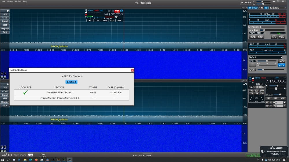
I am trying simultaniously using SSDR 3.10.10 and TeensyMaestro at local network with FR-6600.
PC, FR-6600 and TeensyMaestro has different ip addresses.
When SSDR is running then TeensyMaestro can not connecting to FR over network and goes reboot every time.
When SSDR is OFF then TeensyMaestro connected to FR and functioning properly. In this case if SSDR starting then TeensyMaestro goes to rebooting.
Any suggestion are welcomed.
73! Oleg
0 -
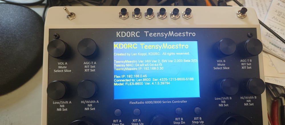
Hi Oleg, Thanks for the screen shot, that makes it much easier to understand. The TeensyMaestro is in stand-alone mode which makes it a GUI client. This will happen if the TeensyMaestro is started before SmartSDR is running. It is important for SmartSDR to be running first.
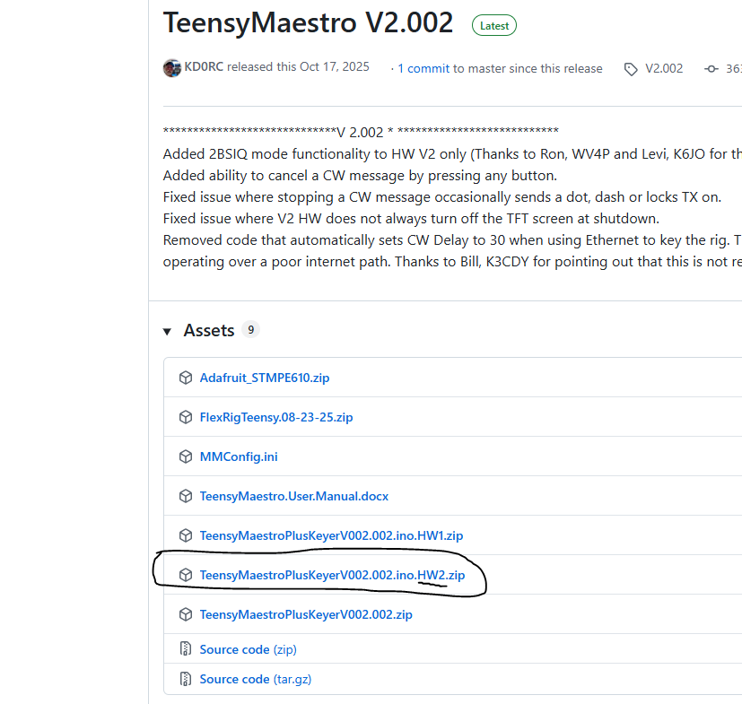
The first thing to check is the TeensyMaestro version. It needs to be on SW Version 2.002. If you built it using Simon's schematic, it will be HW V2. If you built it from the original schematic, it will be HW V1.
If it continues to reboot, or gets stuck on the splash screen, it is an indication that you have a stuck button that is trying to reboot the TeensyMaestro. In this case, try disconnecting the MUX boards to see if the problem clears. If it does, troubleshoot the MUX boards, especially look for a shorted button input.
Here is a link to the latest firmware for HW versions 1 and 2:
Please let me know if this does not fix the issue.
0 -
Len, thank you for reply.
I did try switch ON TeensyMaestro after loaded SSDR and had same situation - TeensyMaestro are rebooting continiously.
At present time Verion is HW ver.1, SW ver. 2.001
I should try load version 2.002.
Now i was downgrade SSDR to version 3.9.19 and all devices functioning perfect.
0 -
Hey @KD0RC Im working on building two units, a v1 and a v2 hardware definition.
The v2 pcbs have the additional io expander pins wired to a connector, does the firmware have configuration parameters to utilize these?
I'm interested in an additional PTT line for a footpedal without paralleling a ptt button. I'm also interested a VFO lock switch or toggle button input.
0 -
Both versions have additional, unused MUX (I/O Expander) pins that are currently unused. I have recently used a few for SO2R and 2BSIQ contest operation, but the rest are still free. There is no code behind the unused pins, but if you are willing and able, you can write your own functionality. I provide the source code on the GitHub page so that you can go after it if you wish.
The V2 board already pulls out the PTT signal in two places, one for the PTT button mounted on the TeensyMaestro box, and another designed to be an RCA socket on the back that you can plug a footswitch into. They are in parallel. Is there a reason that you don't want them in parallel?
The V2 board has another cool feature - the I2C bus is brought out to a set of pins so that you can add additional multiplexers or other I2C devices.
I am curious why build a V1 and a V2? The V2 is quite a bit cheaper, thanks to Simon's (NV0E) PC board set. It is also soooo much easier to build than to do all the point-to-point wiring that I did on V1.
0 -
I purchased the parts and had a v1 50% assembled many months ago. I just havent had the time to work on assembly.
When Simon released the v2 PCBs I ordered a set and again haven't had time to sit down to assemble.
As for not paralleling, I prefer point to point connections for easier wiring and troubleshooting.
I think I saw the ino files in the release package but I don't think I saw them in the GitHub repo?
0 -
Ah, I understand. On the V2 board, there are already two cable headers for PTT, so you are all set there.
Here is a link to the latest source:
It is in the Releases section of the GitHub page.
0 -
Hello,
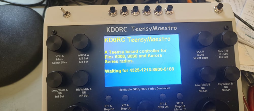
I just finished building my TeensyMaestro (Got the kit from G7UFO). Basically it seems to work. At least it does connect to my Flex 8600. After that it only displays the initial screen. If I touch the screen or any buttons and knobs nothing happens. Neil thought that eventually the display is to tight against the front panel. I removed the front panel, but nothing has changed. Does anybody have an idea what could be wrong?
vy 73 de DF1SD, Kuno0 -
Hi Kuno, did you load HW version 2 to the Teensy?
0 -
Hi Len,
yes I did. It is also displayed on the initial screen.
vy 73 de DF1SD, Kuno0 -
Hello,
this morning I did reload the firmware, but nothing has changed. By the way, in the previous append I forgot to mention that the ON/OFF button is the only one which is working. Looks like a basic problem since none of the other buttons and knobs are working. What is supposed to be displayed after the initial screen? Will a slice be automatically displayed?
vy 73 de DF1SD, Kuno0 -
Hi Kuno, Just to be sure, this is the firmware that you loaded, correct?
If that is OK, then let's look at your MMConfig.ini SD card.
Do you have a Connect statement? It is optional, and if mis-typed will stop the connection. You can set it to ANY, remove it, or comment it out.
Connect: ANY ; 0720-1014-6400-xxxx ANY will connet to the first Flex 6000 or 8000 that it finds. Put in a serial number to select a specific radio.
Here is the progression of screens that you should see:
I wonder if you have a stuck button, solder splash, or that kind of thing. Can you verify that you do not have a button that is stuck ON? You might want to completely remove the front panel to be sure nothing is binding.
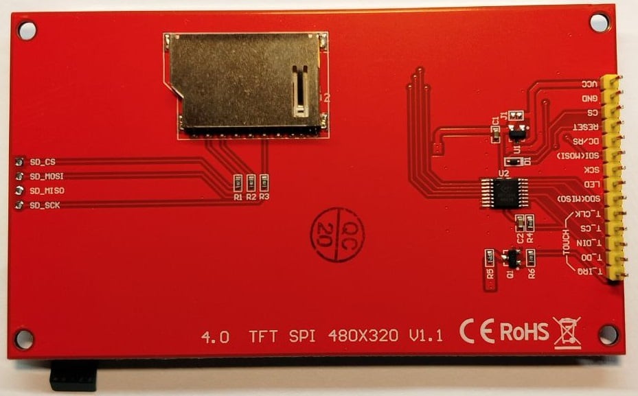
Also, did you remove the SD card socket from the back of the display?
0 -
Hi Len,
I strictly followed the Builders Guide and the Wiki. MMCONFIG.INI is basically the same as distributed, I just changed the callsign. I again checked my soldering and try to test it without the case. But still same behavior. Next I tried to use it as standalone. After the connection to my Flex it enabled the Flex external speakers. I pressed the menu knob for at least half a minute and suddenly a saw a screen with SSB filter selection. I even couldn't return to the previous screen and I'm also not able to recreate this situation. I checked that there is no short circuit below the display. Any other idea?
vy 73 de DF1SD, Kuno0 -
Hi Kuno, can you post a short video of the display as it boots up?
0 -
Hi Len,
it seems that I can not upload an attachment here. Can I send the video to your email address at QRZ.COM? The video is rather large, close to 100 MB.
vy 73 de DF1SD, Kuno0 -
Hi Kuno, it might be better to post it to YouTube, then post the link here.
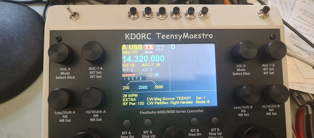
I did find a problem that I will work on after Winter Field Day - Version 2.002 will crash if there are more than two slices open. My 6400 always worked great, but my 8600 only works with slices 0 and 1.
Which Flex do you have?
0


Leave a Comment
Categories
- All Categories
- 390 Community Topics
- 2.2K New Ideas
- 661 The Flea Market
- 8.4K Software
- 157 SmartSDR+
- 6.5K SmartSDR for Windows
- 186 SmartSDR for Maestro and M models
- 439 SmartSDR for Mac
- 275 SmartSDR for iOS
- 265 SmartSDR CAT
- 204 DAX
- 386 SmartSDR API
- 9.4K Radios and Accessories
- 54 Aurora
- 297 FLEX-8000 Signature Series
- 7.2K FLEX-6000 Signature Series
- 971 Maestro
- 58 FlexControl
- 867 FLEX Series (Legacy) Radios
- 945 Genius Products
- 472 Power Genius XL Amplifier
- 347 Tuner Genius XL
- 126 Antenna Genius
- 308 Shack Infrastructure
- 216 Networking
- 468 Remote Operation (SmartLink)
- 142 Contesting
- 814 Peripherals & Station Integration
- 144 Amateur Radio Interests
- 1.1K Third-Party Software