SmartSDR v4.2.20 | SmartSDR v4.2.20 Release Notes
SmartSDR v3.10.15 | SmartSDR v3.10.15 Release Notes
The latest 4O3A Genius Product Software:
The latest 4O3A Genius Product Software and Firmware
If you are needing assistance with FlexRadio products, please refer to the product documentation or check the Help Center for known solutions. Need technical support from FlexRadio? It's as simple as creating a HelpDesk ticket.
Remote Operations - Lightning Rig Saver

Hello Flex Users,
Please see the attached PDF file if you are interested in building a "Lightning Rig Saver". I got to thinking over the past couple of weeks that it would be nice to automatically disconnect my antennas and power from my rigs when there was lightning in my area. After a few brain farts I came up with a design and built a prototype which actually works great. Pictures of the prototype are in the PDF file. I am currently improving the design for ease of build and more flexibility. For those using Node-Red; you can imagine the flexibility of this system to protect and give status on your equipment. Please voice your opinions and suggestions in this thread.
Thanks,
Dave.
K5OZ
Comments
-
@Dave K5OZ very nice work! I can't wait for the .stl files.
1 -
Thank Lou,
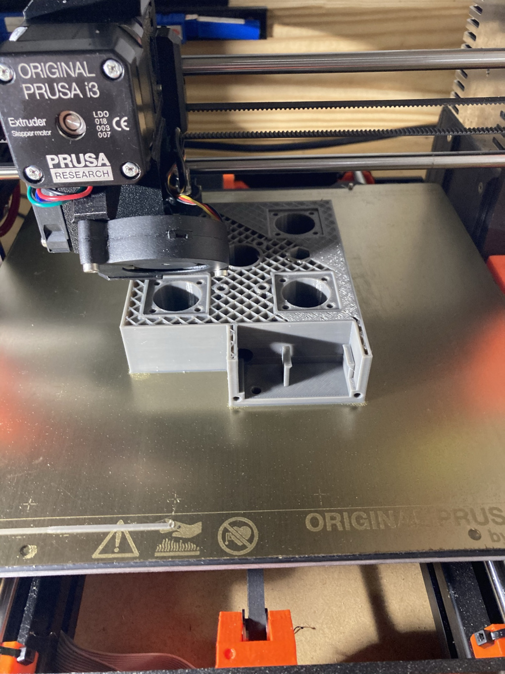
it’s work in progress. The printer is busy printing the next revision now. Here are some pictures:
 0
0 -
Another picture with the prototype on top the flex 6600:
 0
0 -
Added Isolation/Grounding Diagram to documentation. Will update pdf later with diagram.
 0
0 -
Ok remoter’s
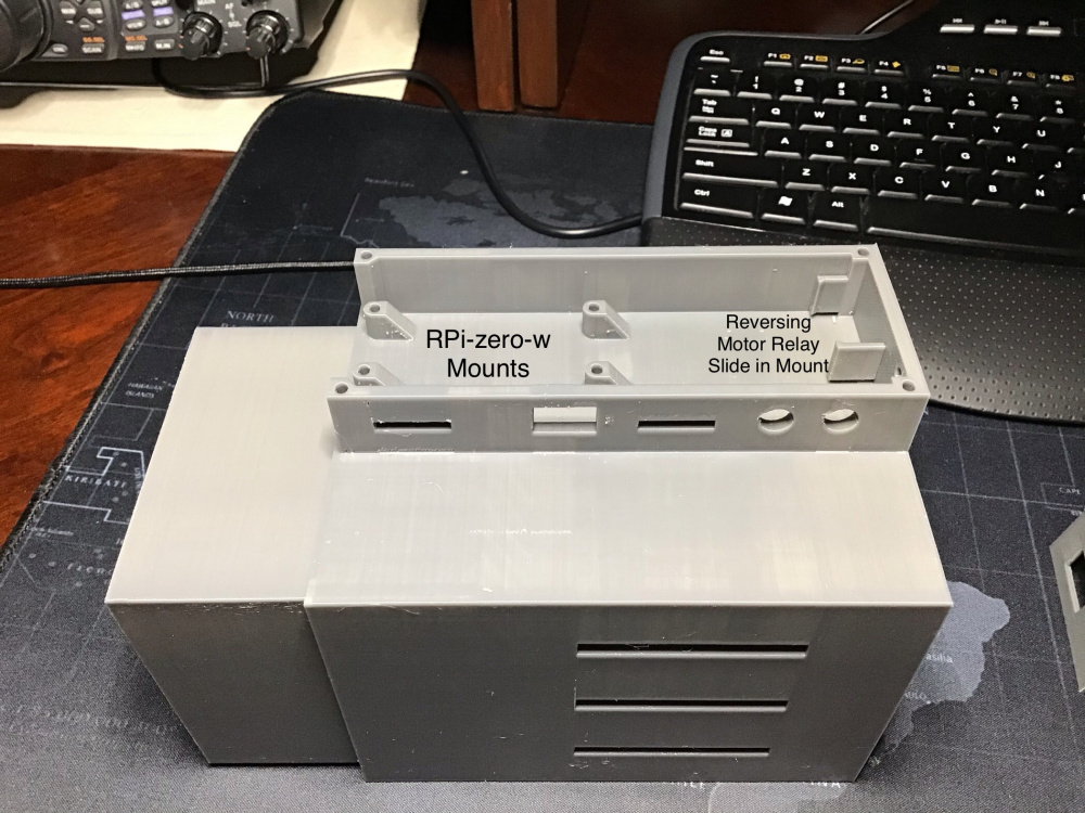
The attached pictures shows the second revision of the printed Lightning Rig Saver enclosures (LRS). Modified the RPi location so you can easily remove the micro-SD and the power input plug will not hang over the side. Added a “Press in” mount for the Motor Reversing Relay. Modified the LImit Switch mounts so that they are very close to the needed position for connect and the maximum distance for disconnect.
Once my new parts arrive in about three weeks, I will put this production unit together, test it and if all goes well will publish the *.stl and Node-Red *.json files. Will be keeping the Prototype for future development.

 0
0 -
Updated *.pdf file correcting some errors:
0 -
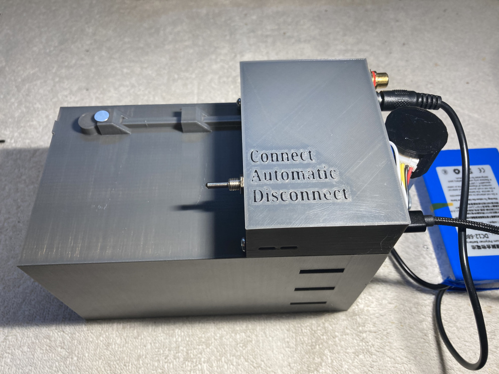
Okay Remote Flexer's, I have finished the first production unit that will be in use at my QTH. It works like a champ.
Dave
K5OZ

See attached pdf file of assembly notes. The *.stl files will be placed on thingiverse. https://www.thingiverse.com/thing:4634806
0 -
This question may be due to my lack of understanding, but if the lightning has just created a path from cloud to earth, perhaps thousands of feet, how can a 3 inch gap prevent discharge to the radio?
1 -
Geoff,
The 3" gap only has to handle the difference between the antenna system ground (which is grounded outside at its base before entering your house) and your house ground at the power service entrance. This is a much lower voltage than between the antenna and cloud; thus all energy should go into your antenna ground rod to be dispersed into the ground and not through your rig and house ground.
0 -
 0
0 -
Dave
Your device is a great enhancement to protecting our Flex Radios. However, you should consider there is another flow path thru the station RF ground to earth ground (antenna ground), you are not showing.
You also need to have/show a #6 CU bonding cable between the "Antenna Ground" rod and the "Utility Service Ground".
Without that bonding cable, there will be a DC current path (delta V) from the Antenna Ground thru your station RF ground, to the Flex Chassis, thru the negative post of the DC supply, to the negative post of your power supply, to the power supply chassis, to the safety ground of your power supply to the point of first disconnect from the utility supply to the utility service ground.
Its get complicated, especially when you throw in the weird frequencies which lighting occurs.
You could simply eliminate the Station RF ground path by also opening up the station RF ground strap to the station ground rod using your device.
You still need the bonding cable between earth grounds to the bonding bus of the first utility disconnect device, per Electrical Building Codes.
The Flex and your 13.8 VDC power supply will be the weak points in the chain.
Alan
WA9WUD
1 -
Alan,
You thinking is correct; however, did you notice the Lightning Rig Saver (LRS) does disconnect the RF grounds and station ground to the antenna box? See attached isolation diagram below from the pdf file. The antenna's RF hot and ground, rig and power supply ground are completely isolated from the antenna/antenna ground via an air gap.
With the addition of a WiFi controlled contactor in your dc power line (hot and common) you can also disconnect your rig from the mains (PS) if you like to. BTW, I don't recommend a WiFi Controlled three legged contactor to disconnect the mains power from the power supply because of the NEC rule to have a "continuous ground path". With this device and WiFi controlled isolation of the PS lines is the equivalent of pulling the plugs from your radio and isolating it completely. The only thing it won't do is put the rig in a faraday cage for a nuclear EMP...LOL.
I agree that it would be better to tie the utility ground and the antenna ground together (underground, outside). This would reduce the voltage differential between antenna ground and utility ground even more. However, in some locations, this is extremely difficult to do without dishing out a large sum of money for the copper and getting the unobstructed trenching required.
 0
0 -
Dave
You are correct, my bad, I did not see your station RF ground disconnect. Well done!
If you need a Node-Red flow for anything, I may be able to help. Let me know. Send me an e-mail.
Alan. WA9WUD
1 -
Thanks Alan for the complement! Looks like you know a lot about Lightning Protection Theory also!
Yes, I could use some Node-Red help, especially on how to get the Pi-Zero to send a signal to the FlexRadio via WiFi to inhibit the TX when the LRS has disconnected the antennas. Right now I am using the LS output into the Flex TX inhibit RCA jack. Would like to eliminate this extra wiring if possible. I will email you the Node Red code I have now.
Dave, k5oz
0 -
Dave,
This is outstanding, and something I have wanted to build for quite some time.
Thanks for the design and for your willingness to share it.
73,
Doug K4DSP
1 -
Thanks Doug,
It's a good project to build if you have access to a good 3D printer or know someone that does and is willing to print it.
BTW, I am already being helped by a fellow Flex community member - Alan (WA9WUD) - on a more powerful Node-Red GUI flow that can be used as an interface to this unit by those already using Node-Red interface to their Flex's.
FYI, I will be off the air (internet) here in about 3 hours as Zeta passes directly over my house. Then i will bet I will be without power for several days.
Dave
k5oz
0 -
Hi Dave,
Thanks for your explanation. There are quite a number of variables involved. What do you estimate the maximum voltage to be at the shack end of the coax? How can you guarantee the ground at the base of the tower will limit the voltage to a safe value?
Even though in my part of the country lighting is rare, I would like to better understand the mechanisms involved.
Best of luck through and after Zeta.
0 -
Dave,
Depending on the exact location of the strike relative to the antenna system and the service entrance panel and the grounding system I can assure you that the 3" gap is not nearly enough, 3+ feet was not nearly enough either. And not all of the lightning energy will be dispersed by the antenna system ground rod.
I found that out in a very dramatic way on September 7 1980 @ 2:05 AM. My antenna system and its ground system was isolated from the electric service entrance grounding system as shown in the diagram. The antenna leads came to the same area that the grounding cable near the window outside the shack.
Long story short, all but about 2 pieces of my equipment that I had at that time was destroyed or damaged. Along with some extension cords etc. And there is still a scorch mark on the radio desk that I was using at the time.
Bottom line was that even though there was a ground rod for the antenna, there was still enough energy to be dissipated that it tried to equalize across an over 3 foot air gap and then through my various pieces of gear and via the household wiring to reach the electric service entrance grounding system. Keep in mind that the electrical service entrance ground is bonded to the utility's grounding system that extends for miles via good conduction paths. So what NEC Article 250 and specifically NEC 810 calls for is not an option, but a laws of physics requirement. No doubt most insurance adjusters would likely see it the same way.
So consider that the isolation box you built path to your gear, and then to various electrical outlets or any other grounded items in the shack room, or under its floor etc., that those may indeed be a lower impedance path for the lightning energy to equalize across than the comparatively high resistance earth ground path between the antenna ground system and the utility ground system.
The cost of bonding the antenna ground system and its grounding rod(s) to the service entrance grounding system is worth every penny. While NEC 810.21 says to use not less than 6 AWG copper, I personally would use nothing smaller than 4 AWG for any bonding between grounding systems.
Duane
N9DG
1 -
Hopefully Dave will return soon following Hurricane Zeta. In the meantime, I uploaded our Node-Red flow for control of the switch.
Dave uses a Pi Zero on the switch. We tried running my flows with a dashboard, and the poor little Pi was exhausted trying to run the dashboard. So, we split up the load.
We now have two flows. One for the main "Station Pi" presumably a Pi three or above and a flow for the remote, Pi Zero, operating the switch relays. Requires an MQTT broker to be installed somewhere. I suggest running "Mosquito" on one of your station Raspberry Pi. Protective features are included to monitor the TCP connections.
The Flow also has provisions for sending e-mail and text messages showing all important status information on weather, disconnect switch position, Flex TX Inhibit Status, and health of the Raspberry Pis.
Here is a screenshot of the dashboard. The tile background colors change to show status:

Alan - WA9WUD
1 -
Hello Geoff, Duane and Alan,
The last 48 hours have been one heck of a ride. Zeta's outer bands started hitting us about 5 pm with very heavy rains, by the time the eye wall hit us at 7 pm we had 4 to 5 inches of rain. When the eye hit it was like laying on the ground next to a west bound freight train...a little humbling. After the front of the eyewall passed their was an eerie silence outside and you couldn't hear any traffic, animals nor people...a literal calm before the storm situation. Then the backend of the eye hit and we hung on as another train passed us going east bound on the tracks. It was not as loud as the west bound train but, none the less, still a little scary. Our house was built with the new hurricane standards and we survived without major damage. A few downed pines and branches all over...but none hit the house. The roads are now passable because the trees that fell on the powerlines/roads have been removed by the utility companies. My camp in the marsh land (Lake Catherine Island, near Lake Borgne) took a pretty good hit, but it also survived with only missing hand rails busted doors and some vinyl ceilings ripped off on the porches. I will be spending weeks out there fixing it backup once power is restored.
Geoff, Duane and others:
This device is not meant to take a direct lightning strike to your antenna system, although it is the next best thing and could possibly protect you against one. For a direct lightning strike protection you would need massive ground system like those used in a broadcast tower lightning protection system with the RF hot lines that have 1/4 shorted stubs inline with the antenna. This is not practical with multi-frequency antennas used in most Amateur operations. The system I have offered here is the next best solution to protect your remote rigs. By disconnecting your Rig from the antennas, antenna grounds and house power/grounds you do not give the lightning impulse a path to travel through your rig.
Geoff, Duane
The voltage potential across the 3 inch gap depends on the earthing resistance/conductance at your location. Note that the breakdown of air at sea level is ~ 228,600 volts for a 3 inch gap. If your antenna ground is tied to your Utility ground via an underground 6 or better gauge wire the resistance of the earth is not that critical; i.e., you are close to a single point ground and the absolute max voltage potential across the 3 inch gap will only be about 75kv (assumes a normal lightning bolt with 300 MV and 30,000 amps, half dispersed in the antenna ground rod and other half traveling underground through the connecting ground cable to the utility ground rod). I believe this is the worse case because in reality most of the bolt will be dispersed in the antenna ground rod if the ground is of normal conductance. Now if the antenna ground is not directly tied to the utility ground there may be more of a voltage differential between house ground and antenna ground. How much is hard to calculate because of the many variables present; i.e., how much energy the antenna rod/earth can absorb, the conductance of the ground, how far away the utility ground is from the antenna ground, etc.
Duane,
Your solution to tie the antenna ground to the utility ground is good and sound! If you can do it, you should do it. This will minimize the delta potential voltage differences during a strike between antenna/ground and house utility ground. My opinion is that this Lightning Rig Saver (LRS) system is the next best thing to broadcast station grounding. Most hams cannot afford broadcast station grounding solutions, but should be able to afford (in many cases) tying both antenna ground and utility grounds together with a number 6 ga. or better. With the aforementioned done, this system could possibly take a direct strike and your rig survive. Of course your antenna, coax down through your antenna grounding box may be charred a little. LOL.
Alan,
We need to TeamView some more to get some bugs out of the Pi-zero/Pi4 interface that I have noticed. Sunday maybe my next available time to do it.
Thanks to all for their inputs!
73 for now,
Dave, K5OZ
0 -
Dave,
I printed the enclosures this weekend. No issues printing on a cheap-o Ender 3 printer using PLA. After a bit of light sanding and cleaning the inner section slides in and out very nicely. Now that I have the enclosure I will scrounge/order the rest of the parts.
Thanks again for the design. It is clear that you put some thought into making it easily printable.
73,
Doug K4DSP
 2
2 -
WOW Doug that looks excellent and a 1st class enclosure. Looks like a great project to build.
Any chance of building them and selling them for others who don't have a 3D printer available?
I for sure would be interested in one or two.
Thanks and always good to see you on here, been a long time since i called and talked about the RBI Kenwood remote controller.
1 -
Doug, it most certainly looks good! Another tight area you should check is the PL259 entry’s. Just see if a patch cord will fit into the coax holes. I now have a revision coming out that makes it easier to disassemble the coax on the rig side without having to take it apart. After I print it and check out all the parts I will update the *.stl files on Thingiverse.
By the way, how long did it take to print with PLA?
Dave
k5oz
0 -
Doug,
After looking closer, the threads look a little ragged in the center of the inner box. You may want to see if a 3/8” 16TPI bolt or tap will clear them out.
Dave
0 -
Bret, I think you're confusing me with my old friend Doug Hall WB8YOJ from Ohio. Both of us are named Doug Hall, both hams, both designed signal-to-noise voters, both worked in the mainframe networking world, both did VoIP stuff, and both married nurses. Kind of uncanny the number of similarities. At trade shows we used to refer to each other as Doug Hall 1 and Doug Hall 2.
If you want one of Dave's lightning switch enclosure sets (and if it's OK with him) you might be better off downloading the stl files and going to treatstock.com. It's a 3D printing broker site where you browse by price and location and then order the parts. Their prices are reasonable and they have a good reputation. I would not feel right about selling Dave's enclosure since I didn't design it
Dave, the inner part took approximately 14 hours to print, and the outer part took 21 hours. This was on a Creality Ender 3. Used approx. 395 grams of PLA.
Incidentally I just saw where the Ender 3 was on sale from Creality for $157 incl. shipping. Not a bad deal.
73,
Doug K4DSP
0 -
Yep, Sorry
Back into my closest
0 -
Doug and Bret,
This design is for the Ham Community at large. As long as someone does not try to commercialize it I encourage Hams to duplicate for friends and charge a reasonable amount for time and material.
Dave
0 -
A comment about push-on RF connectors.
I have been using push-on male to female UHF type adapters for several years. I have run 1200 to 1500 watts through them during SO2R RTTY operation. Occasionally I would reach over and see if I could detect any heat. So far I have detected no heating. In my situation I use them to manually disconnect the coax from a bulkhead plate where the coax enters the house. So, they should be fine at QRO levels. I should mention that I bought the first ones at a Hamfest and the quality was poor. I found another source with much better quality and those have worked for several years.
73, Mark K5XH
1 -
Mark,
That is good news because I eventually want to get an amplifier for my station.
Thanks for answering the QRO question I had!
73,
Dave
0 -
Hello everyone,
See attached for Version 2 of the Lightning Rig Saver (LRS). I modified the unit to take care of some issues that I noted in the version 1 design. Below is a list of improvements:
- Found and fixed a “sneak circuit” for lightning in the disconnect Limit Switch (LS) being close to the Antenna coax connectors
- Improved the air gap to approximately 4.5 inches;
- V1 voltage breakdown to LS was < 30KV
- V2 voltage breakdown now is > 340KV
- Incorporated magnetic linkage to limit switch for failsafe disconnect limit
- Incorporated an Electronics enclosure to make it easier to assemble, disassemble and experiment with encoder feedback if desired
- Reduced Outer Box rig coax dimensions to enable connection of coax without disassembly
- Changed pictures to show updated design and build
- Version #2 *.stl files will be loaded on thingiverse.com
- Node-Red files updated by Alan WA8WUD for local only or remote w/GUI
- Added three position switch to manually connect and disconnect

 1
1


Leave a Comment
Categories
- All Categories
- 401 Community Topics
- 2.2K New Ideas
- 690 The Flea Market
- 8.6K Software
- 197 SmartSDR+
- 6.6K SmartSDR for Windows
- 200 SmartSDR for Maestro and M models
- 460 SmartSDR for Mac
- 279 SmartSDR for iOS
- 268 SmartSDR CAT
- 220 DAX
- 395 SmartSDR API
- 9.6K Radios and Accessories
- 112 Aurora
- 348 FLEX-8000 Signature Series
- 7.2K FLEX-6000 Signature Series
- 999 Maestro
- 58 FlexControl
- 872 FLEX Series (Legacy) Radios
- 975 Genius Products
- 482 Power Genius XL Amplifier
- 358 Tuner Genius XL
- 135 Antenna Genius
- 322 Shack Infrastructure
- 227 Networking
- 483 Remote Operation (SmartLink)
- 146 Contesting
- 847 Peripherals & Station Integration
- 147 Amateur Radio Interests
- 1.1K Third-Party Software