SmartSDR v4.1.5 | SmartSDR v4.1.5 Release Notes
SmartSDR v3.10.15 | SmartSDR v3.10.15 Release Notes
The latest 4O3A Genius Product Software:
The latest 4O3A Genius Product Software and Firmware
If you are needing assistance with FlexRadio products, please refer to the product documentation or check the Help Center for known solutions. Need technical support from FlexRadio? It's as simple as creating a HelpDesk ticket.
Arduino Library and examples

while I am writing my homebrew Arduino Controller code, I realized that I
could share the basic part of my code for Band Data and CAT usage. I
read some posts on the Community from people asking for a particular kind of Band Data system like I2C, BCD, RS-232 and so on. Waiting for other manifactures to adopt the Flex native ethernet protocols, you could use this library to command already existent devices. This library really doesn't implement a specifica protocol, but give you a very simple way to do it.
The code is open and free and is provided in three parts: a basic library that works at the ethernet level and two library examples that show you how you can use the libraries for band data and CAT purposes.
The software also does not implement any set command but only the commands required from other devices to get the radio status.
So you need to have knoweldge of SmartSDR Ethernet API, SmartSDR Command Line API, Arduino and C programming.
The Basic library is essentially a small piece of software that implements the SmartSDR Discovery Protocol to locate and connect a FlexRig in your network. In default mode the library try to locate the first FlexRig available in the network, then it try to establish a connection using the 4992 Tcp-IP port. This approach is correct if you have only one Flex Rig (like in my case).

If you have more than one Flex Rig on the same network, you have to manually set the serial number of the rig you want to connect to.


When the radio has been located, the library starts a connection over the 4992 TCP/IP port. It is used to command the radio and receive streaming status information. Every update on the internal state of the radio is then reflected on the library objects.

Going more in depth, a parser analyzes the TCP/IP packets, selecting only the Status "S|" one and then pass any updates to the local software objects.
In this way, using the library, you can access the internal state of the rig without having to deal with network protocol.
The library can handle the objects shown in the picture below. As you can see the number of slices, panadapters waterfalls is limited only to two as I did tests only on my Flex-6300. The library can be extended to monitor the status of multiple objects as in the case of 6500 and 6700 Radio. The ATU is also a missing object because my 6300 isn't equipped with it and I have never tested it.
To use the library you need a really powerful micro-controller. I choose Arduino Due because it is very simple to program and has a C standard instructions set. Also you need an Arduino Ethernet Shield that uses the W5100 chip. It is the best board that allows your Arduino to access the network at 100Mb/s. It is also the board that has the best support libraries.
== Banda Data Library Example
Band Data library relies on the previous library and it generates events you can simply handle from inside you sketches. You don't need to worry about basic rig communication, nor you are requested to handle all your logic in the main loop() routine.
Simply, in the setup() procedure, you have to register a function (handler) for each event that you need to handle. The library do the rest.
You can register your code for the following events:
- Any update on Slice objects (only # 0/1)
- Any update on Panadapter objects (only # 0/1)
- Any update on Waterfall objects (only # 0/1)
- Any update on Radio object
- Any update on Transmit object
- Any update on Interlock object
After having registered your event handler, the library execute a call to it, each time that particular event occurs. In the handler routine you can activate your hardware or you can use strategies to monitor your system.
Last but not least, as you can have access to a great number of Flex object properties, you can extend the library code to handle events based on a particular object properties.=== CAT RS232 Library Example
I have only implemented the commands that can be useful for external devices synchronization, mostly amplifiers and dynamic antennas controller. I do not own any of these devices so I did tests using other software like Omnirig and LOG4om. It seems it works nicely, but be careful, you have to do your own test.
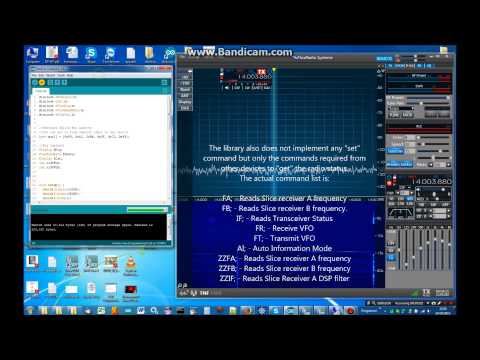
The library also does not implement any set command but only the commands required from other devices to get the radio status.
Below you can see the actual command list:
FA; - Reads Slice receiver A frequency
FB; - Reads Slice receiver B frequency.
IF; - Reads Transceiver Status
FR; - Receive VFO
FT; - Transmit VFO
AI; - Auto Information Mode
ZZFA; - Reads Slice receiver A frequency
ZZFB; - Reads Slice receiver B frequency
ZZIF; - Reads Slice Receiver A DSP filter
Basic
Band Data Example
CAT Example
Calling these "library" is a bit pretentious and the purists of the C / C ++ might blame me looking at my code. But it seems the code works and is open. So if you like, you can change and improve it. Just let me know.
Last, I recorded a video to show you how you can use the software.
73' Enzo
iw7dmh
 https://www.youtube.com/watch?v=kcI3jm1opB0
Comments
-
Fantastic tutorial. Grazie mille Enzo.0
-
Thank you Enzo for sharing this. Excellent work.
0 -
Fantastic. Thanks for the information. Now I can plan something for my Arduino that doesn't involve turning LEDs on and off. Thanks!
1 -
Well, my Arduino controler is nearly ended.
Here is a test in the field during a contact with 5Z0L Kenya Expedition.
It works fabulously with smooth heavy metal vfo and very responsive meters.
Most of SSDR controls are already implemented and of course it works also without a computer.
It is amazing thinking that only 120 Kb of C/C++ code can handle most of the Flex Rig power.
73' Enzo
iw7dmh https://www.youtube.com/watch?v=WTA3E0qdD0I
1 -
Very nice. Have you made any changes to your library?
I'm getting ready to roll out my magnetic loop controller changes this weekend. It watches the flex and automatically sets the vacuum variable capacitor position. My project was pretty far along when you posted your library. I did try it but was getting negative numbers for frequency. The compiler complained about a missing dtostrf file, which I did find. Work travel and various other priorities prevented me from looking at it again. If you've made no changes, then I'll try debugging it this weekend before I no longer have the ethernet shield to test with.1 -
Enzo, well done! I will send my pre-order deposit ASAP!
:-)
james
WD5GWY
0 -
Which board are you using? Uno or Due? Uno uses a 8bit Atmega328 proc, while Due use a 32-bit ARM processor, so they have a different compiler.
Please let me know and if needed I'll try to compile my libs for the Uno board.
73'
Edit: compiling for UNO board is no more possible as the whole program size go over 32K. This is the compiler error I get when I switch form Due to Uno board.
Sketch uses 47,174 bytes (146%) of program storage space. Maximum is 32,256 bytes.0 -
Imagine what can we do with the super-equipped Maestro
")
keep our breath ...
73'
0 -
I was using the MEGA 2560.0
-
Ok, so you can compile the code adding a comment to line n. 16 in the library header file FlexRig.h, but it should not solve the negative number issue as ATmega2560 is an AVR 8bit class processor and treats integer in different way .
I don't own any 2560 board so I can't run any additional test.
Anyway, also compiling and running well on AVR class board, you should find performance issues as the parsing code is really very heavy.
That is the reason I chose a more powerful ARM board.0 -
That probably explains it. For the application I'm using it for, the mega is performing quite well. I only parse a few very specific items and only subscribe to slice events. With the 6300 I only have 2 slices to watch. For frequency, all I need is 3 decimal places, so I don't need such a large number. From the time I change the frequency to the time the stepper starts moving is usually well under a second. My biggest performance issue is waiting for the stepper to traverse the length of the 25 turn capacitor. For a UI application I can see the need for a faster platform. For a back end application like a magnetic loop controller, an 8 bit Arduino works just fine. The best part is I didn't have to deal with c/c++ code.
Thanks to the work you and a few others in this community have done, I think the development of 3rd party apps is going to really start taking off much faster now. Fun stuff!0 -
Please, at the end of your work, consider the idea to share your code.
It could be helpful for other friends that would like to experiment.
73' Enzo
iw7dmh
0 -
I'll create a separate post on it in the next few days. It's really nothing much to look at
Steve0 -
Hello,
during my holidays I found the time to update my Arduino libraries.
The main feature is that you can compile it on both AVR (Mega) and ARM (Due) boards.
In addition the library embeds the whole set of event handlers and the basic rig object (fRig) exposes the most important setter methods.
In this way you can interact with the rig without having to deal with the underlying Ethernet APIs. Anyway it is required a very good knowledge of the FlexLib Apis.
I hope this can help.
73' Enzo
iw7dmh2 -
Excellent news. Thank you!
0 -
Enzo,
Hi, I am also grabbing band data and sending it to GPIO and I2C using a BeagleBone Black.
I was going to look at your code but the Band Data Example does not exist on the link above.
Was it removed?
thanks,
Phil K3TUF
0 -
Yes. It is because in the new library all the event handlers are already implemented. Unfortunately I can't update my first post so I can't remove the broken link.
Anyway you can download it from my Dropbox dir.In the example directory you'll find a configured project (FlexSignature.ino). Just open it with the Arduino Ide and start coding all the events you need. In the project you can find a specific file for each Flex Object:
- G06_RadioEvents.ino
- G07_EqEvents.ino
- G08_InterlockEvents.ino
- G09_TransmitEvents.ino
- G10_PanadapterEvents.ino
- G11_WaterfallEvents.ino
- G12_SliceEvents.ino
The Object-Properties table is shown below.
For example if you want to be notified of each Transmit Frequency change you have to:
- open the G09_TransmitEvents.ino (object=Transmit - property=freq);
- uncomment the proper attach_<property>() statement (each attach method is in the configure<Object>Events() function);
in this example the correct statement is fRig.transmit.attach_freq_event(onTransmit_freq); - uncomment the related handler function on<Object>_<property>();
in this example the function is:
void onTransmit_freq() {
Serial.println("onTransmit_freq() event!");
} - implement your business code in the event handler.
If you want to be notified of each SliceFrequency change you have to:
- access the G12_SliceEvents.ino (object=Slice- property=RF_frequency);
- uncomment the proper attach_<property>() statement (each attach method is in the configure<Object>Events() function);
in this example the correct statement is fRig.slice[i].attach_RF_frequency_event(onSlice_RF_frequency);
- uncomment the related handler function on<Object>_<property>();
in this example the function is:
void onSlice_RF_frequency(const int senderId) {
Serial.print("onSlice_RF_frequency("); Serial.print(senderId); Serial.println(") event!");
}
Note that each Slice, Waterfall and Panadapter event handler has a parameter called "senderId". You can use it to find the object that fired the event.
For example, a senderId=0 means the RF_Frequency event has been fired from the Slice A, while a senderId=1 means the RF_Frequency event has been fired from the Slice B. - implement your business code in the event handler.
After having registered your event handler, the library execute a call to it, each time that particular event occurs. In the handler routine you can activate your hardware or you can use strategies to monitor your system.
0 -
Hi Enzo, I'm wanting to use your excellent work to talk with my magnetic loop controller. From other projects I have several genuine 2650's and ethernet shields. When I try and compile the flexsignature.ino or test.ino for the 2650 all goes fine. When I try and program it using the IDE, it fails with the dreaded <stk500_2_receivemessage timeout>
I then switched to my USBASP using the ISP header. I did get it to take once, but further changes to the code seem to cause it to fail. I'm still able to push other programs into all of the 2650's, however they all fail on flexsignature libs.
I've looked for the <!!!> or <21,21,21> which on old bootloaders would cause fails but I don't see any of that. I've upgraded the bootloaders and searched the google but I have not found a resolution.
Any suggestions?
73 de Dave, va3ae
0 -
Hello Dave,
it seems an issue related to hw communication board and not to sw libraries.
I never had this particular trouble so I can't help you but it seems there is a lot on internet about it. Take a look here http://forum.arduino.cc/index.php?topic=49663.0
I hope this can help.
73' Enzo
iw7dmh
0 -
Enzo
Do you know if an arduino could be used to provide the control signals the PowerSDR and the SDR1000 send over the parallel port. I'd love to find a way to communicate with my SDR1000 without 32bit windows and a PC parallel port. Sorry, if this turns out to be a dumb question.
73, Jay - NO5J0 -
Hi Enzo, I managed to get the 2650 to take code.
I used my USBASP programmer pointed avrdude at the code. (this is from a Win7 box, but the same happens from my Ubuntu Laptop)
To document the fun, I will put this bit of output for anyone who may have suggestions or insights.
I imagine we will solve it, and with me it is usually something obvious that I missed....
######################################################################
This is the Flexsignature.ino compile
I expected to see some events as I changed things on the FLEX-6500, but i do not
##########################################################################
=== Started DHCP request
=== Waiting for IP address
IP address is: 192.168.2.166192.168.2.166
===Looking for Flex Rig (UDP)===
=====>0915-4055-6500-6717
===========Flex Rig=============
IP Address:192.168.2.165
Model Name:FLEX-6500
Serial:0915-4055-6500-6717
Version:1.4.16.6
NickName:=6500-VA3AE c
connecting to Flex rig:192.168.2.165.
Connected
==VERSION (connect)==
1.2.0.0
==HANDLE (connect)==
E679FE19
==>LISTENING FOR VITA49 PACKETS
######################################################################
This is the Test01.ino compile
avrdude.exe -c usbasp -p m2560 -P usb -b 115200 -B 0.5 -U flash:w:"sketchTest01.cpp.hex":a
It connects, but seems to reset, as many as four times The C2 "Euro" symbol is also puzzling....
##########################################################################
=== Started DHCP request
=== Waiting for IP address
IP address is: 192.168.2.166
===Looking for Flex Rig (UDP)===
=====>0915-4055-6500-6717
===========Flex Rig=============
IP Address:192.168.2.165
Model Name:FLEX-6500
Serial:0915-4055-6500-6717
Version:1.4.16.6
NickName:=6500-VA3AE c
connecting to Flex rig:192.168.2.165.
Connected
==VERSION (connect)==
1.2.0.0
==HANDLE (connect)==
3E7F623B
==>LISTENING FOR VITA49 PACKETS
Connected to Flex Rig
C0|sub tx all
C1|sub atu all
C2€
##################################################################
0 -
0
-
I also could not find the Band Data Example.0
-
As I pointed before, Band Data code is embedded in the library.
In my answer to Phil, K3TUF, you can see som usage example.
73' Enzo
iw7dmh
0 -
@Dave,VA3AE
>...
>I expected to see some events as I changed things on the FLEX-6500, but i do not
>...
The log you have dumped confirm that your board can connect your Rig. well done
To see the events please follow the example I posted above (read my answer to Phil, K3TUF).
Consider that, using the FlexSignature.ino, all the events are already implemented but they are also commented. This saves a lot of memory and you only need to comment out the handler you need: band, frequency, mode, and so on.
Test01.ino is intended for connection test purpose only.
73' Enzo
iw7dmh0 -
Jon
With the SDR1000 all that is really needed is a device that ouputs the control signals as a parallel port would. PCI/E parallel port cards work. USB-parallel cables don't, with the exception of the Flexradio USB/IO cable that looks like it's just a USB adapter cable, but contains some additional hardware.
The SDR1000 is not a printer.
Another complication is that PowerSDR expects to be connected to either a real parallel port, or the Flex USB/IO device.
A further complication is that Microsoft no longer supports this sort of communication in 64 bit versions of Windows. CNC machines also used this setup between computer and CNC machines. and are having similar problems with 64bit windows.
I'm really just curious if an Arduino might be the solution since it might be possible to program it's input and output to emulate a USB/IO device. PowerSDR and DTTSP are open source so it might be possible to reverse engineer a solution.
I sort of hoped Enzo's reply would be "Of course it can, been there done that.
That Elecraft Band Decoder interests me for other projects though.0 -
Enzo
Do you know if an arduino could be used to provide the control signals the PowerSDR and the SDR1000 send over the parallel port. I'd love to find a way to communicate with my SDR1000 without 32bit windows and a PC parallel port. Sorry, if this turns out to be a dumb question.
73, Jay - NO5J
Virtually you can implement any logic in a Arduino board.
A band decoder project usually requires an input line from the rig and one or more output lines for third part devices.
If your idea is avoid a 32bit windows pc you need to implement the CAT protocol in the Arduino board. For this purpose things are more complicated as you need a USB host shield and a USB-RS232 adapter: in this scenario the Arduino board is a host device and you cant' use the standard RS232/USB port (that is a client port).
On the output side, instead, you can use any of the output ports to drive the DB25 lines.
73' Enzo
iw7dmh
0 -
Hello,
I would like to point out that the library project is developed using genuine or compatible arduino.cc products (and its related sw libraries).
This clarification is necessary because it could happen you buy accidentally products from the arduino.org line that could not work properly with my FlexRig code.
Of course my library is open and you can change it as you like, but using .org products I can't give you a great support.
This is the negative effect due to Arduino splitting event.
73' Enzo
iw7dmh0 -
Hi Enzo, I've tried a number of coding experiments over the last week, and done a fair bit of reading, of the FLEX Documents and on the sometimes unpredictable characteristics of the Mega2650.
If this work can help some others, then this week's effort will be worth it to me. Here is what I have learned:
If I understand correctly, certain patterns contained in my compiled Hex code are mis-interpreted by the bootloader as reserved instructions, or maybe it's just jibberish.
This happens when I perform the standard upload via USB/UART port.
Accordingly, I can bypass that and use the ISP/ICSP (In Circuit System Programmer) or as I learned in College <To connect directly to the board and Whack the device with raw code>.
Now, I have several parameters to pass to avrdude to get it to behave:
bin/avrdude -C%ProgramFiles(x86)%Arduinohardware oolsavr/etc/avrdude.conf -vvvv -patmega2560 -cusbasp -Uflash:w:%HOMEPATH%appdataLocalTempuild8021697898052857256.tmp/sketch/FlexSignature.cpp.hex:i
This seems to get the code into the device reliably, and I make sure it erases the flash and does a verification pass on each upload of about 82K - Lots of free space remains. Of course the %BUILD-DIR% changes every time we recompile, but alas, such is the world of Micro$oft.
Next, I have tried several calls to events using your nicely organized layout. I've concentrated on G06_RadioEvents and G12_SliceEvents. My other Arduino Program/Hardware will parse that output and use it as input to instruct the hardware to tune the antenna stepper/SWR measuring system and to toggle a set of 9 relays to switch control lines and coax feeds. Eventually I will watch for events and potentially even issue commands in special conditions. This all works now via CAT over serial but the Ethernet control is required for the Flex.
Unfortunately I have not been able to make the FlexSignature.cpp.hex return any values for configured slice events - onRadio_slices - onSlice_RF_frequency or even onSlice_in_use. I've defined and uncommented the relevant sections. I've checked the code several times and even started again from the beginning with a fresh untar to make sure I hadn't unintentionally shot myself in the foot.
I receive in the serial monitor the connect, the version, the Handle and the message "==>LISTENING FOR VITA49 PACKETS"
However nothing seems to be returned when I change parameters an the radio.
There is also still an unexpected letter _c after the Nickname, and I admit I am still puzzled why I don't get a proper "hello world" from the Arduino.
At this point I am thinking that the Mega2650 is just not the piece for this job; it has quirks and this may be a demonstration of that nature.
I've thought of trying to run the code in an emulator and tracing but I haven't had time to research any of that yet. The default Arduino IDE is pretty bare bones, it can't even step or breakpoint the code, so I have some more stuff to learn about how to do more advanced troubleshooting.
Enzo, you have had success with the Arduino Due and it may be I would need to go that route to recreate your success.
It is a bit of a shame that I have spare 2650's that I thought I could put to the task.
Again, if anyone has suggestions, I am all ears.
I paste the output below.
73 de Dave, VA3AE
===========Flex Rig=============
IP Address:192.168.2.165
Model Name:FLEX-6500
Serial:0915-4055-6500-6717
Version:1.4.16.6
NickName:=6500-VA3AE c
connecting to Flex rig:192.168.2.165.
Connected
==VERSION (connect)==
1.2.0.0
==HANDLE (connect)==
A6705F55
==>LISTENING FOR VITA49 PACKETS
0 -
Hello Dave,
thank a lot for your in depht analysis. I have very low experience on Mega boards, so I need more time to repeat all the test. As I said before I am working on the cat multiplexer project, using just a Mega board. At the end of my work I'll have a better knowledge of the pro and cons Mega boards. Of course I'll share with you any (if any) progress.
73' Enzo
iw7dmh
0


Leave a Comment
Categories
- All Categories
- 390 Community Topics
- 2.2K New Ideas
- 661 The Flea Market
- 8.4K Software
- 157 SmartSDR+
- 6.5K SmartSDR for Windows
- 186 SmartSDR for Maestro and M models
- 440 SmartSDR for Mac
- 275 SmartSDR for iOS
- 265 SmartSDR CAT
- 204 DAX
- 386 SmartSDR API
- 9.4K Radios and Accessories
- 54 Aurora
- 297 FLEX-8000 Signature Series
- 7.2K FLEX-6000 Signature Series
- 971 Maestro
- 58 FlexControl
- 867 FLEX Series (Legacy) Radios
- 945 Genius Products
- 472 Power Genius XL Amplifier
- 347 Tuner Genius XL
- 126 Antenna Genius
- 308 Shack Infrastructure
- 216 Networking
- 468 Remote Operation (SmartLink)
- 142 Contesting
- 814 Peripherals & Station Integration
- 144 Amateur Radio Interests
- 1.1K Third-Party Software